Vertical cavity surface emitting laser device
a laser device and vertical cavity technology, applied in the direction of lasers, laser shape and construction, semiconductor lasers, etc., can solve the problems of defect level within the photonic band gap, problem becomes critical, etc., and achieve the effect of suppressing thermal problems due to the thickness of the reflective mirror layer
- Summary
- Abstract
- Description
- Claims
- Application Information
AI Technical Summary
Benefits of technology
Problems solved by technology
Method used
Image
Examples
first embodiment
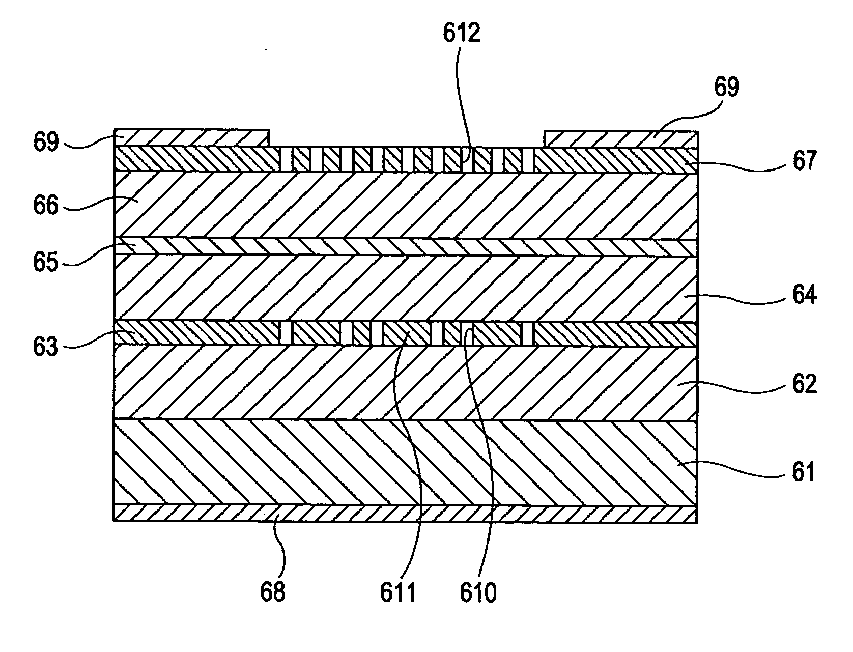
[0127] The structure of a laser device according to a first embodiment will now be described with reference to FIG. 6.
[0128] A lower cavity mirror light confinement layer 62, a lower cavity mirror layer 63, a lower cladding layer 64, an active layer 65, an upper cladding layer 66, and an upper cavity mirror layer 67 are sequentially laminated on a substrate 61. An n-electrode 68 and a p-electrode 69 are provided on the reverse face of the substrate 61 and on the top face of the upper cavity mirror layer 67, respectively.
[0129] The substrate 61 is an n-type GaAs substrate having a thickness of 565 μm. The lower cavity mirror light confinement layer 62 is composed of n-type Al0.7Ga0.4As and has a thickness of 1 μm. The lower cavity mirror layer 63 is composed of n-type Al0.4Ga0.6As and the lower cladding layer 64 is composed of n-type (Al0.5Ga0.5)0.5In0.5P. The upper cavity mirror layer 67 is composed of p-type Al0.4Ga0.6As and the upper cladding layer 66 is composed of p-type (Al0....
second embodiment
[0149] The structure of a laser device according to a second embodiment will now be described with reference to FIG. 9. A lower cavity mirror light confinement layer 92, a lower cavity mirror layer 93, a lower cladding layer 94, an active layer 95, and an upper cladding layer 96 are sequentially laminated on a substrate 91. A current narrowing layer 99 is provided so as to surround a part of the lower cladding layer 94, the active layer 95, and a part of the upper cladding layer 96. An upper cavity mirror layer 910 is further laminated on the upper cladding layer 96. An n-electrode 911 and a p-electrode 912 are provided on the reverse face of the substrate 91 and on the top face of the upper cavity mirror layer 910, respectively. The substrate 91 is an n-type GaAs substrate having a thickness of 565 μm. The lower cavity mirror layer and the lower cladding layer are composed of n-type Al0.4Ga0.6As and (Al0.5Ga0.5)0.5In0.5P, respectively. The upper cavity mirror and the upper cladding...
third embodiment
[0167] A third embodiment will now be described with reference to FIGS. 11A and 11B. Since the structure and the materials of the laser device itself are the same as those in the second embodiment, only the structure of the cavity mirrors will be described. The production process is also the same as that of the second embodiment.
[0168]FIGS. 11A and 11B are schematic views of lower and upper photonic crystal mirrors of the third embodiment, respectively, viewed from a direction perpendicular to a planer surface. As shown in FIG. 11A, in the lower cavity mirror, holes of a basic photonic crystal structure are provided in the entire surface, and defects formed by removing the holes are arrayed at the center. Parameters of the basic photonic crystal structure are the same as those of the lower cavity mirror of the second embodiment. This embodiment is characterized in the array of the defects. These defects are arrayed according to a specific regularity but arrayed aperiodically. Rough...
PUM
 Abstract
Description
Claims
Application Information
 - R&D
- Intellectual Property
- Life Sciences
- Materials
- Tech Scout
- Unparalleled Data Quality
- Higher Quality Content
- 60% Fewer Hallucinations
Browse by: Latest US Patents, China's latest patents, Technical Efficacy Thesaurus, Application Domain, Technology Topic, Popular Technical Reports.
© 2025 PatSnap. All rights reserved.Legal|Privacy policy|Modern Slavery Act Transparency Statement|Sitemap|About US| Contact US: help@patsnap.com


