Radio communication system
a technology of communication system and radio, applied in the field of radio communication system, can solve the problems of deteriorating communication quality and increasing commutation error rate, and achieve the effect of reducing reception errors
- Summary
- Abstract
- Description
- Claims
- Application Information
AI Technical Summary
Benefits of technology
Problems solved by technology
Method used
Image
Examples
first embodiment
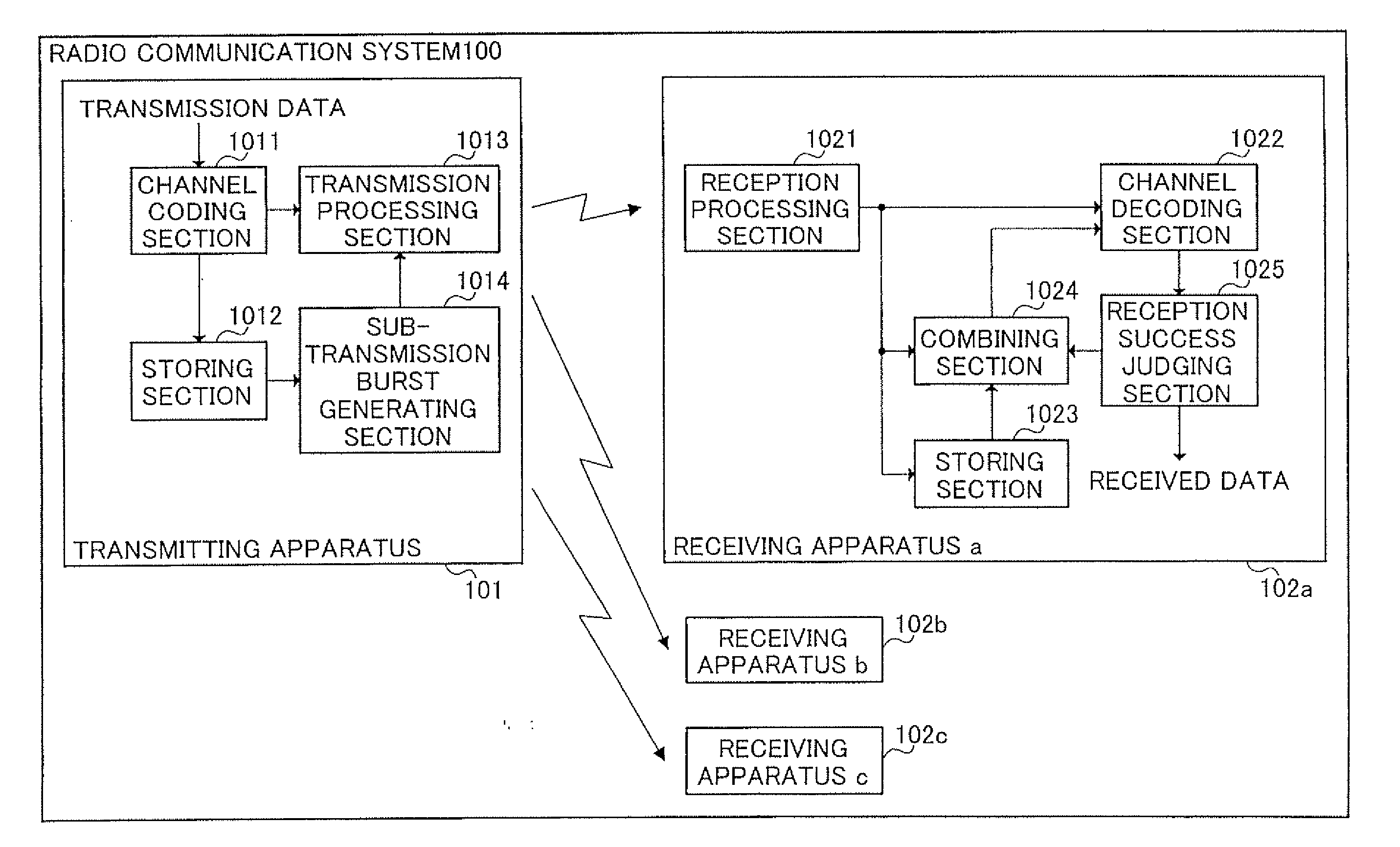
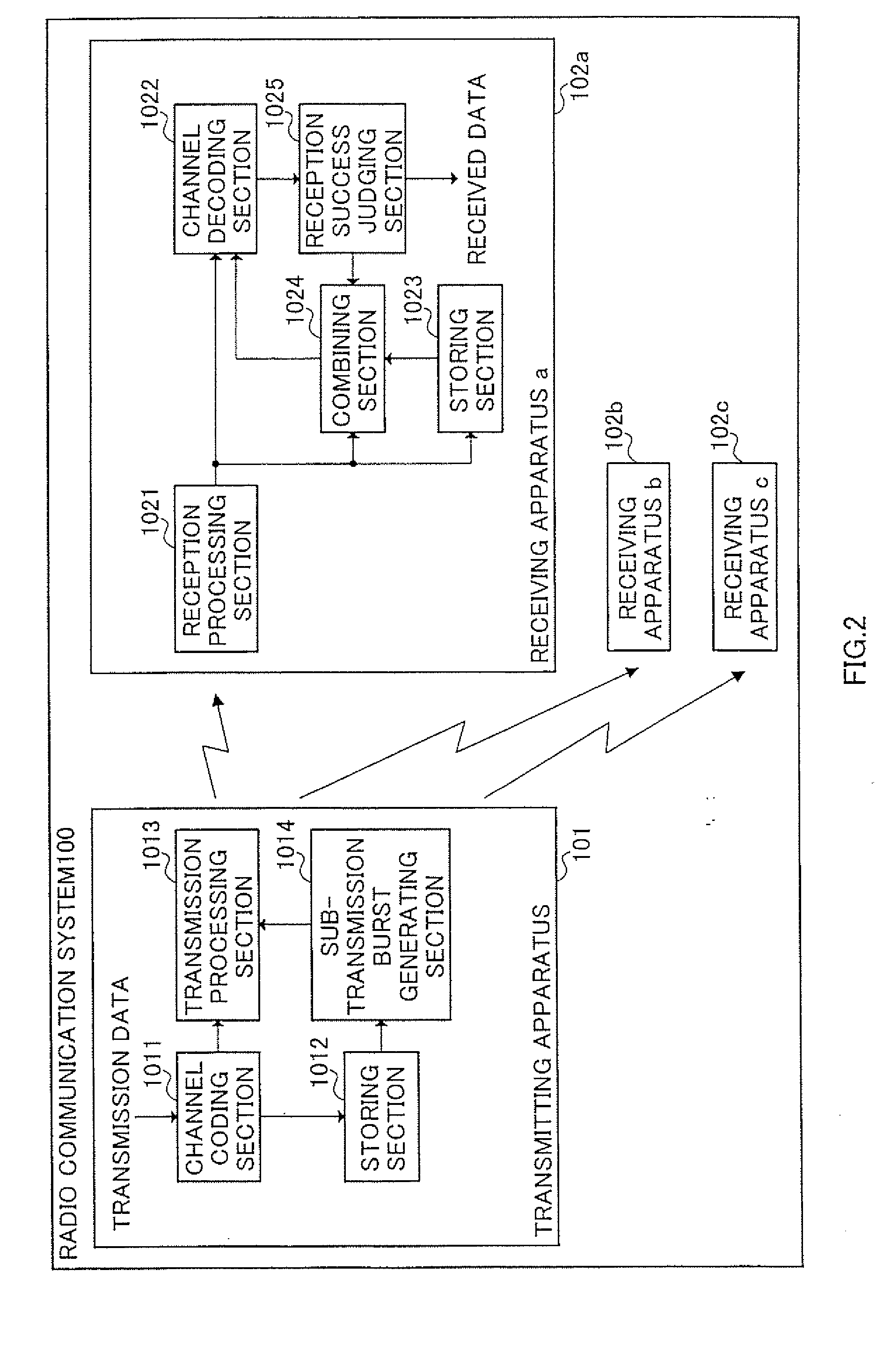
[0029]FIG. 2 is a block diagram illustrating a configuration of a radio communication system according to the first embodiment of the present invention.
[0030] In radio communication system 100, transmitting apparatus 101 transmits radio signals of data to transmit, and has at least channel coding section 1011, storing section 1012, transmission processing section 1013 and sub-transmission burst generating section 1014.
[0031] Channel coding section 1011 performs on the data to transmit processing such as, for example, addition of error detecting code, convolutional coding, puncture processing and burst generation. In this embodiment, as an example, CRC parity code is added, the convolutional coding with a coding rate of ½ and the puncture processing of a puncturing rate of ¾ is performed, and accordingly the coding with a total coding rate of ⅔ is performed except CRC.
[0032] Storing section 1012 stores the whole or part of a coded data sequence in a coding step in channel coding s...
second embodiment
[0056]FIG. 5 is a block diagram illustrating a configuration of a radio communication system according to the second embodiment of the present invention. Radio communication system 300 is such a system that enables bidirectional radio comminations, and is composed of a plurality of transmitting / receiving apparatuses, i.e., apparatuses 301 and 302, each provided with the transmitting / receiving function.
[0057] In this embodiment, a communication link from transmitting / receiving apparatus 301 to transmitting / receiving apparatus 302 is referred to as downlink, and a constitution is explained for improving the communication quality on downlink. Transmitting / receiving apparatus 301 has at least channel coding section 3011, transmission processing section 3012, storing section 3013, reception processing section 3014, received quality information extracting section 3015, and partial period data retransmission processing section 3016.
[0058] Channel coding section 3011 performs channel codi...
third embodiment
[0074]FIG. 6 is a block diagram illustrating a configuration of a radio communication system according to a third embodiment of the present invention.
[0075] Radio communication system 400 is such a system that enables radio communications by M-ary modulation scheme, and is composed of a plurality of transmitting apparatuses 401 and receiving apparatuses 402.
[0076] Transmitting apparatus 401 performs the M-ary modulation on transmission data and further performs the transmission and partial retransmission in accordance with a predetermined frame format, and at least has quadrature amplitude modulation (QAM) transmitting section 4011, storing section 4012 and partial retransmission processing section 4013. QAM transmitting section 4011 performs the quadrature amplitude modulation on transmission data and performs the transmission and partial retransmission in accordance with a predetermined frame format, and it is assumed in this embodiment that as an example of the quadrature ampli...
PUM
 Abstract
Description
Claims
Application Information
 - R&D
- Intellectual Property
- Life Sciences
- Materials
- Tech Scout
- Unparalleled Data Quality
- Higher Quality Content
- 60% Fewer Hallucinations
Browse by: Latest US Patents, China's latest patents, Technical Efficacy Thesaurus, Application Domain, Technology Topic, Popular Technical Reports.
© 2025 PatSnap. All rights reserved.Legal|Privacy policy|Modern Slavery Act Transparency Statement|Sitemap|About US| Contact US: help@patsnap.com


