
Double air valve recoil dampener for firearms

a recoil dampener and double air valve technology, applied in weapon parts, butts, weapons, etc., can solve the problems of severe recoil that affects the person firing the weapon, the accuracy of the shooter, and the shooter raising the front of the firearm, so as to achieve the effect of absorbing the recoil, and reducing the cost of recoil

Inactive Publication Date: 2006-11-16
SNODERLY RUSSELL M
View PDF5 Cites 42 Cited by
  • Summary
  • Abstract
  • Description
  • Claims
  • Application Information

AI Technical Summary

Benefits of technology

[0027] An advantage of the present invention is that it provides a compact efficient recoil dampener for firearms with a double adjustable air cylinder attached to a rifle butt between the stock and the rubber shoulder pad, which maintains the appearance and normal functioning of a rifle or shotgun while absorbing the recoil effectively with adjustment capability to adjust for different firearms, shooting situations, and individuals and with instant recovery for rapid firing.
[0028] Another advantage of the present invention is that the balance of the firearm is not affected.
[0029] One more advantage of the present invention is that it provides smooth effective shock absorption to dampen the recoil.
[0030] An additional advantage of the present invention is that it prevents suction and backpressure for a fast return of the piston to the original position to enable rapid firing of the firearm.
[0031] A further advantage of the present invention is that it provides adjustment of the damping of the recoil.
[0032] An added advantage of the present invention is that it provides a large amount of recoil dampening with a short run of the piston in the cylinder to minimize the size of the device.

Problems solved by technology

A problem that exists with firearms is the fact that many of them have a severe recoil that affects the person firing the weapon.
In firearms such as shotguns and rifles, the rear end of the butt stock is positioned against the shooter's shoulder and the recoil often causes the shooter to raise the front of the firearm each time the weapon is fired.
Recoil is detrimental to a shooter's accuracy and can result in bruising and pain to the shoulder of the person firing the weapon.
Prior art devices do not adequately address the problem of providing a recoil dampener which is compact and maintains the appearance and normal functioning of a rifle or shotgun while absorbing the recoil effectively with adjustment capability to adjust for different firearms, shooting situations, and individuals.

Method used


Image

  • Double air valve recoil dampener for firearms
  • Double air valve recoil dampener for firearms
  • Double air valve recoil dampener for firearms

Examples


Embodiment Construction

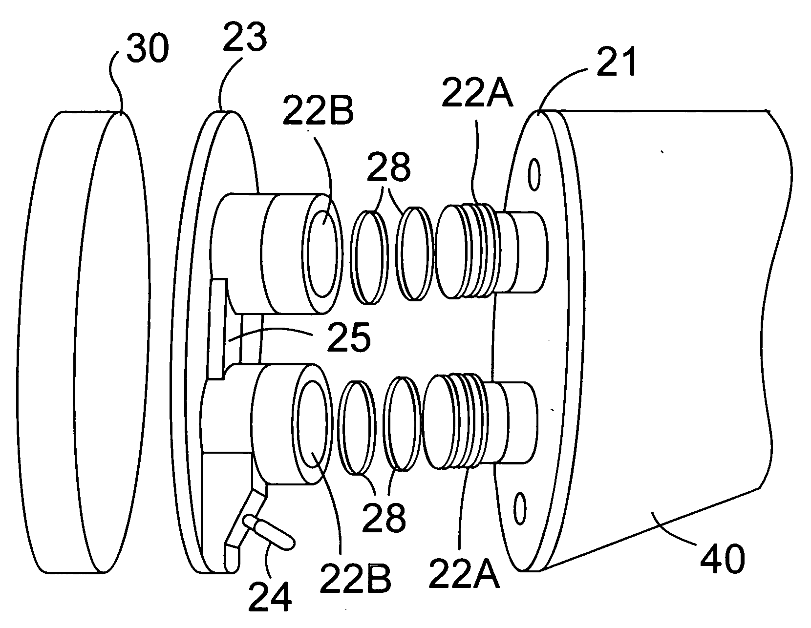
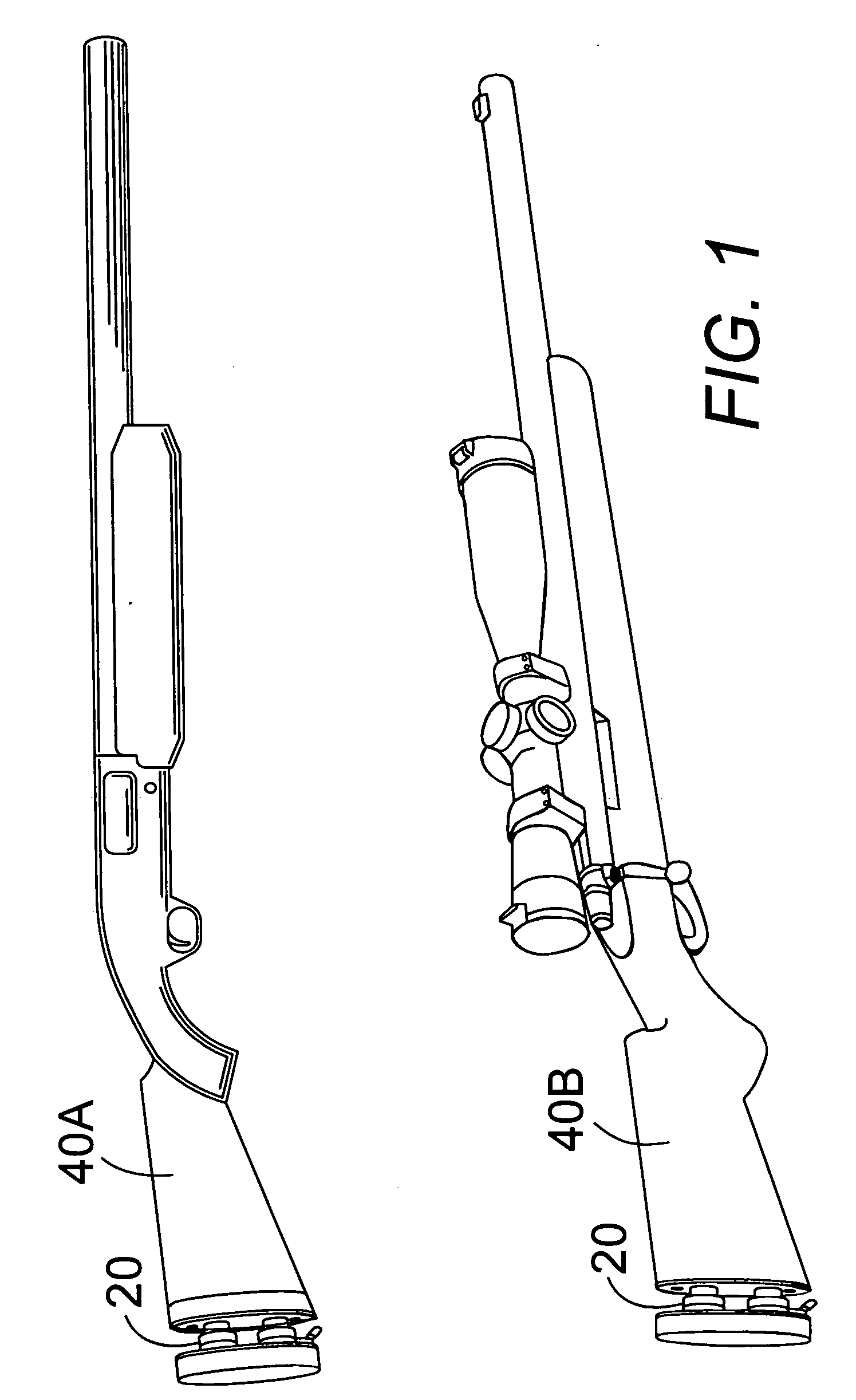
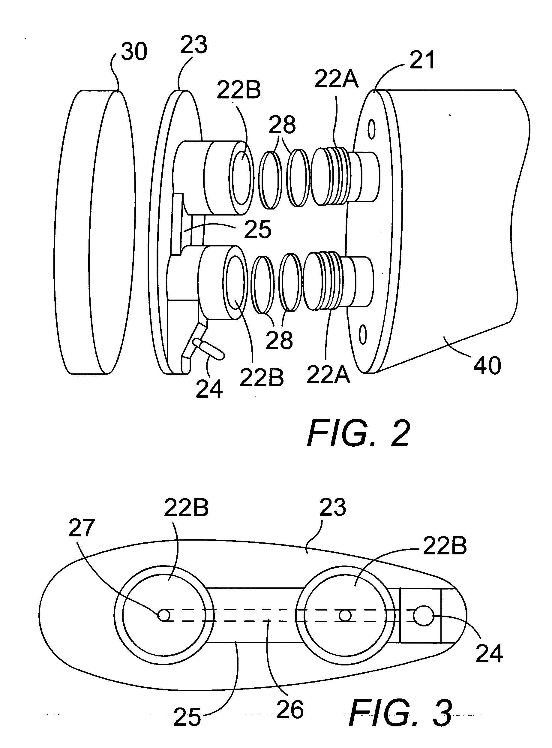
[0039] In FIGS. 1-4, a double air valve recoil damper device 20 for shotguns 40A and rifles 40B comprises a pair of pistons 22A mounted in a pair of cylinders 22B communicating with an air release outlet 26 and air release control valve 24.

[0040] The pair of pistons 22A are spaced apart and rigidly mounted on a butt end of a firearm 40 on a support cap 29 attached by a threaded end 14 screwed into threaded plate openings 15 in a plate 21 which screws onto an end of a rifle butt 40. The pair of pistons 22A each comprise a cylindrical shaft with preferably two circular grooves 18 around a perimeter of an end of the cylindrical shaft receive an O-ring 28 in each of the grooves.

[0041] A mating pair of cylinders 22B are mounted on a plate 23 attached to a shoulder pad 30 for the firearm. The pair of cylinders 22B are sized to receive the pair of pistons 22A with one of the pistons in each of the cylinders fitting with an air-tight slidable fit to compress the air in each cylinder. In F...


PUM


Abstract

A pair of pistons with O-rings are mounted on a plate attach to an end of a butt of a firearm. A pair of cylinders for receiving the pistons are mounted on a plate attached to a shoulder pad and attached to the firearm by having the pistons inserted in the cylinders. An air release hole in a bottom plate of each cylinder communicates with an air outlet having an adjustable air valve to adjust the amount of damping of a recoil of the firearm.

Description

BACKGROUND OF THE INVENTION [0001] 1. Field of the Invention [0002] The present invention relates to recoil reducers for firearms, and particularly to a double air valve recoil dampener for a gun stock which comprises two air pistons each set in a cylinder within the butt of the firearm. [0003] 2. Description of the Prior Art [0004] A problem that exists with firearms is the fact that many of them have a severe recoil that affects the person firing the weapon. In firearms such as shotguns and rifles, the rear end of the butt stock is positioned against the shooter's shoulder and the recoil often causes the shooter to raise the front of the firearm each time the weapon is fired. Recoil is detrimental to a shooter's accuracy and can result in bruising and pain to the shoulder of the person firing the weapon. [0005] Prior art devices do not adequately address the problem of providing a recoil dampener which is compact and maintains the appearance and normal functioning of a rifle or sh...

Claims


Application Information

Patent Timeline
IPC IPC(8): F41C23/00
CPCF41C23/06
Inventor SNODERLY, RUSSELL M.
Owner SNODERLY RUSSELL M
Learn More