Safe efficient outboard motor assembly

a safe and efficient technology for outboard motors, applied in the direction of marine propulsion, waterborne vessels, vessel construction, etc., can solve the problems of less thrust being produced than is optimal, undesirable decrease in performance, and a risk to native aquatic life and people, so as to reduce the rotation of water, save the means of propelling a watercraft, and improve the effect of water flow

Inactive Publication Date: 2006-11-16
INNERSPACE
View PDF6 Cites 2 Cited by
  • Summary
  • Abstract
  • Description
  • Claims
  • Application Information

AI Technical Summary

Benefits of technology

[0006] The present invention includes several novel aspects all of are described herein. One embodiment of and aspect of the present invention preferably includes a drive assembly, a shaft assembly, and a impeller-jet assembly coupled to the shaft assembly. A preferred impeller-jet assembly preferably includes an inlet stator, an exit stator, a propeller, and an external housing surrounding the stators and the propeller. The ends of the blades of the propeller are not exposed to human and marine life, resulting in a safer means of propelling a watercraft. The inlet stator preferably includes a plurality of blades shaped to direct the flow of water into an optimum direction for the propeller. The exit stator also preferably contains a plurality of blades shaped to minimize the rotation of the water imparted by the propeller and develop a more efficient flow of water as it exits the impeller-jet assembly.

Problems solved by technology

The exposed rotating blade presents a danger to native aquatic life and to people.
While there have been attempts at creating guards that encompass the propeller, such guard / propeller assemblies have typically resulted in an undesirable decrease in performance.
In addition, cavitation caused by the spinning propeller of conventional outboard motor assemblies creates inefficiencies that can result in less thrust being produced than is optimal.
At certain propeller speeds, the created cavitation results in a forward speed limit, beyond which creating additional thrust is impracticable since it does not result in any meaningful improvement in the speed of the craft.

Method used


Image

  • Safe efficient outboard motor assembly
  • Safe efficient outboard motor assembly
  • Safe efficient outboard motor assembly

Examples


Embodiment Construction

[0015] In the following description, for purposes of explanation, numerous specific details are set forth that provide a thorough understanding of aspects and embodiments of the present invention. It will be apparent, however, that all of these specific details may not be required to practice the inventions set forth in the claims and that variants of the details can be substituted for many of the specifics to meet the details of the specific application in which the invention may be used.

[0016] In the following description of the preferred embodiments, substantially similar parts are denoted by the same reference numerals. Also, while references such as top, bottom, side, horizontal, and vertical may be used throughout the specification, it is to be understood that their orientation requirements are only to facilitate the explanation of the various embodiments and depending on the application, the top could be the side or bottom or vice versa.

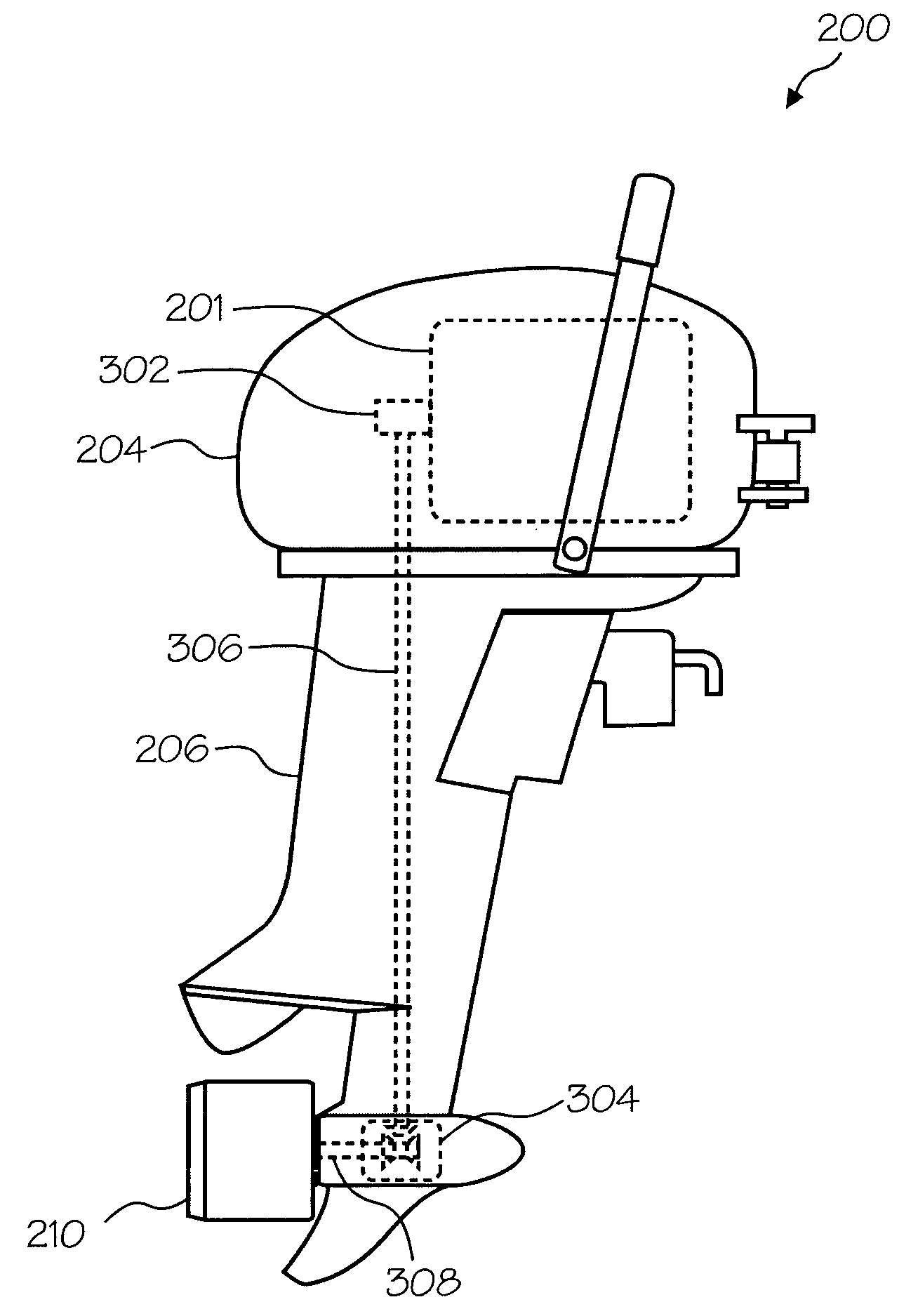
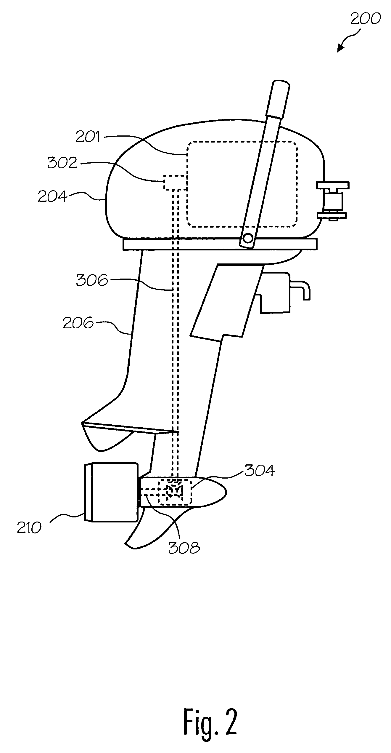
[0017] With reference to FIGS. 2, 3, ...


PUM


Abstract

An outboard motor assembly for use as external propulsion for a watercraft includes a drive assembly, a shaft assembly, and a impeller-jet assembly coupled to the shaft assembly. The impeller-jet assembly includes an inlet stator, an exit stator, a impeller, and an external housing surrounding the stators and impeller. The inlet stator contains a plurality of blades, forcing the flow of water into an optimum direction for the impeller. The exit stator also contains a plurality of blades, which are configured to direct the flow from the impeller, removing the twist and resulting in a more efficient flow of water. The exit stator is tapered to create a more efficient flow of water. The center portion of the impeller contains a hub with an exhaust vent. In the alternative, a duct can be positioned adjacent to the outlet stator such that air is directed into the flow from the outlet.

Description

FIELD OF THE INVENTION [0001] The invention relates generally to propulsion systems including more particularly to a safe efficient outboard motor assembly that can be used with watercraft. BACKGROUND [0002]FIG. 1 is an illustration of a typical conventional outboard motor assembly 100. An internal combustion engine is contained within an engine housing 104. A drive shaft (not illustrated) located within drive shaft housing 106 couples the engine to a propeller 102. As the engine operates, the drive shaft rotates, causing the propeller 102 to rotate. The rotation of the propeller 102 creates a force which causes the boat to which the outboard motor assembly 100 is attached to move. [0003] Conventionally, certain watercraft use the outboard motor assembly 100 to provide propulsion for the watercraft. The propellers of conventional outboard motor assemblies suffer from a number of disadvantages. The exposed rotating blade presents a danger to native aquatic life and to people. For exa...

Claims


Application Information

Patent Timeline
Patent Type & Authority Applications(United States)
IPC IPC(8): B63H11/00
CPCB63H20/00B63H11/08
Inventor GONGWER, CALVIN A.
Owner INNERSPACE
Why Eureka
Try Eureka