
Haptic controller for road vehicles

Inactive Publication Date: 2006-11-16
TRW LIMITED
View PDF3 Cites 15 Cited by
  • Summary
  • Abstract
  • Description
  • Claims
  • Application Information

AI Technical Summary

Benefits of technology

[0006] It is an object of the present invention to improve the haptic information that the driver receives from the steering system and to provide an algorithm using information already contained in the car about the dynamic state of the car, to artificially recreate the steering feel properties described above.

Problems solved by technology

Traditionally these effects have been produced by careful design of the steering system, but modem power assisted steering systems, and space and other compromises in the design of steering systems, has lead to the effects becoming much less noticeable.

Method used


Image

  • Haptic controller for road vehicles
  • Haptic controller for road vehicles
  • Haptic controller for road vehicles

Examples


Embodiment Construction

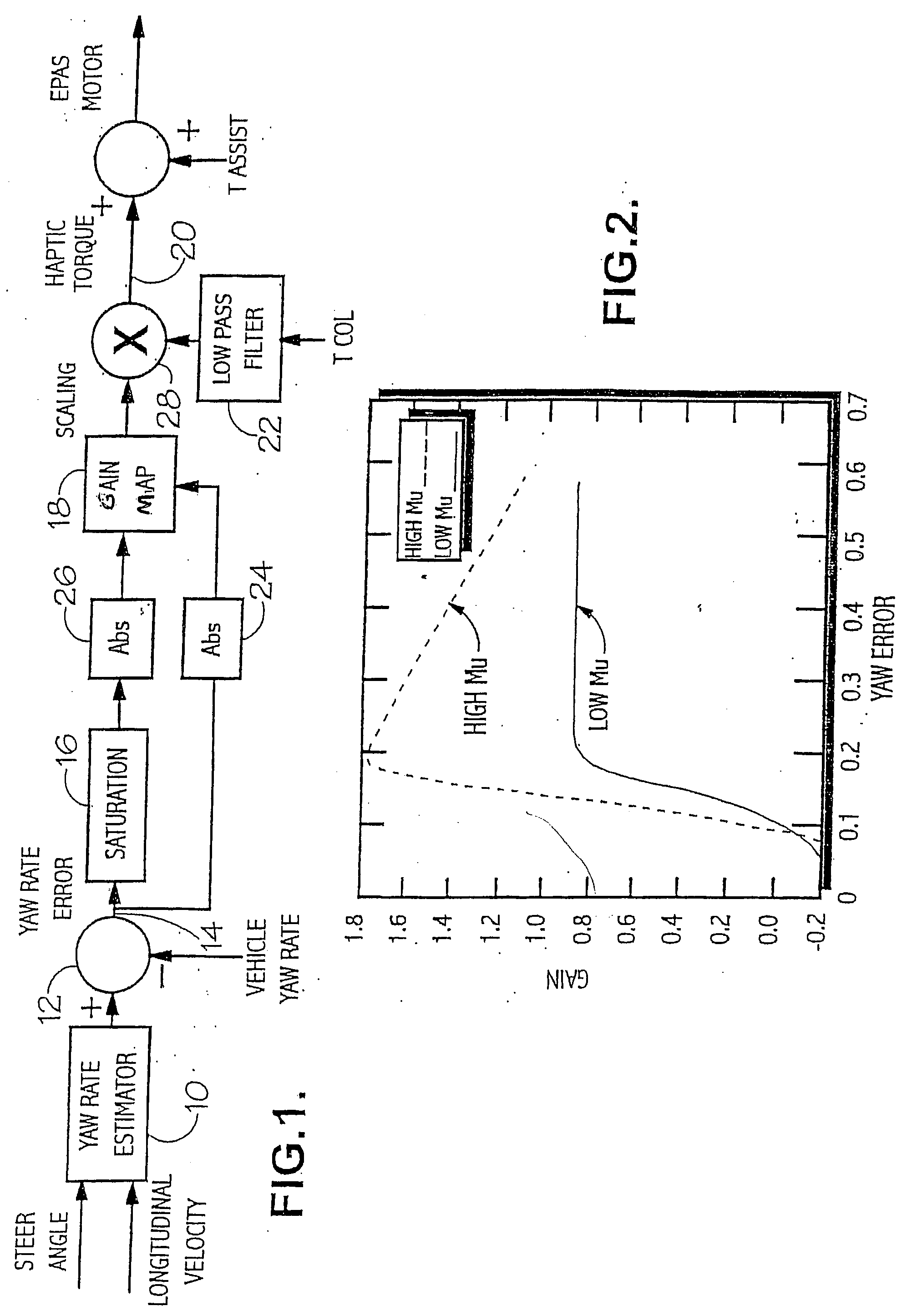
[0039] Referring first to FIG. 1, the vehicle steer angle and longitudinal velocity are input to element 10 where an estimate is established of the yaw rate demanded by the driver of the vehicle. The yaw rate estimation is based for example on the steady state understeer equation, expressed as: r^=Vxl⁡(1+(Vx / Vch)2)⁢δswGs

where Vx is the vehicle longitudinal velocity, l is the wheel base, Vch is the vehicle characteristic speed, δsw is the handwheel angle and Gs is the gain of the steering system from road wheels to handwheel. This estimated value is then passed through a first order low pass filter, tuned to give the estimate similar lag to the vehicle. Careful selection of the break point in this filter allows the point where the steering goes light, in relation to the loss of steer authority to be controlled.

[0040] The resulting estimated yaw rate is compared at 12 with a signal representative of the actual vehicle yaw rate, as measured by a Vehicle Stability Controller (VSC) or...


PUM


Abstract

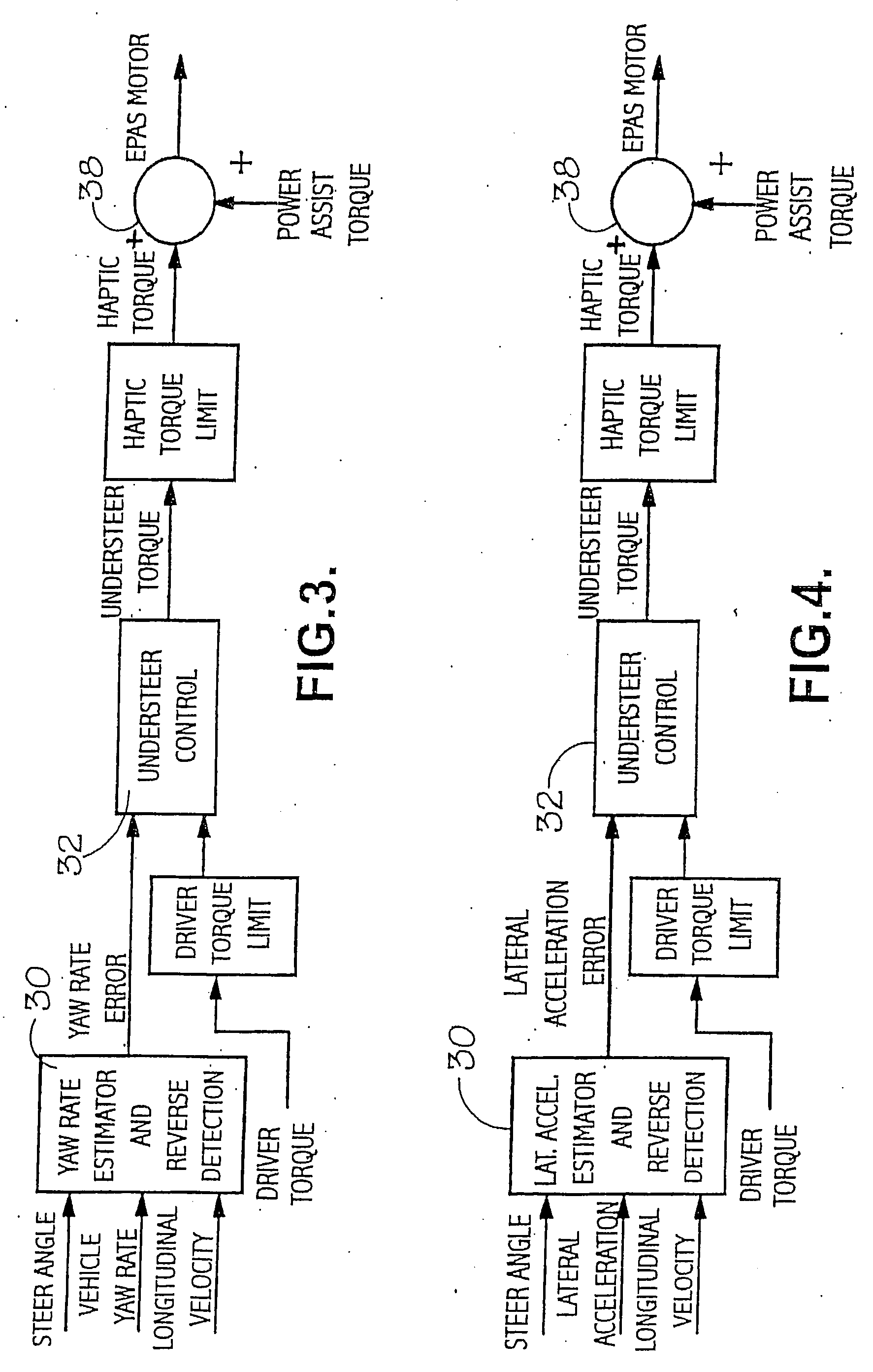
An electric assisted steering system for a motor driven road vehicle, having assist torque signal generating means which generates an assist torque signal for the steering system in response to the driver's applied torque and sensed vehicle speed to reduce the driver's steering effort. A yaw rate haptic torque is generated which is based upon vehicle rate error and is arranged to be added to the torque assist signal such that, when the yaw rate error builds up corresponding to increasing steering instability (e.g. understeer or oversteer) of the vehicle, the haptic torque added to the torque assist signal reduces the effective road reaction feedback sensed by the driver in advance of any actual vehicle stability loss whereby to allow the driver to correct appropriately in good time before terminal steering instability is reached. Alternatively, the haptic torque can be based upon vehicle lateral acceleration which is arranged to be subtracted from the torque assist signal such that when vehicle lateral acceleration builds up, corresponding to tighter cornering of the vehicle, the haptic torque subtracted from the torque assist signal increases the effective road reaction feedback sensed by the driver corresponding to the increase in cornering forces generated by the tyres of the vehicle.

Description

CROSS-REFERENCE TO RELATED APPLICATIONS [0001] This application is a Divisional Patent Application of U.S. application Ser. No. 10 / 637,035 filed Aug. 7, 2003, which is a continuation of International Application No. PCT / GB02 / 00523 filed Feb. 7, 2002, the disclosures of which are incorporated herein by reference, which claimed priority to Great Britain Patent Application No. 0103015.4 filed Feb. 7, 2001, the disclosures of which are incorporated herein by reference.BACKGROUND OF THE INVENTION [0002] The present invention relates to electric assisted steering systems (EAS) in motor driven road vehicles and is concerned in particular with a control system in a road vehicle adapted to provide steering torque compensation or haptic torque based on the measured vehicle dynamics, such as yaw rate or lateral acceleration. [0003] Electric assist steering systems are well known in the art. Electric assist steering systems that use, for example, a rack and pinion gear set to couple the steerin...

Claims


Application Information

Patent Timeline
IPC IPC(8): B62D6/00B62D5/04B62D5/07B62D6/04B62D101/00B62D113/00B62D119/00B62D137/00
CPCB62D6/04
Inventor FARRELLY, JAMES OWEN PATRICKSTEVENS, SIMON DAVIDBARTON, ANDREW DENNIS
Owner TRW LIMITED
Learn More