Pallet

a technology of pallets and boxes, applied in the field of pallets, can solve the problems of reducing the weight of the container, affecting the use and maintenance of the field bin, and causing the damage of the field bin largely, and causing the cost of shipping, periodic cleaning, and repairs

Active Publication Date: 2006-11-23
REHRIG PACIFIC CO INC
View PDF7 Cites 63 Cited by
  • Summary
  • Abstract
  • Description
  • Claims
  • Application Information

AI Technical Summary

Benefits of technology

[0009] One or more of the walls may include a cutout opening upwardly from an approximate mid-height level on the wall. A drop wall or drop door is pivotably connected to the wall in the cutout. A hinge assembly connects the door to the wall and includes a first hinge pin and a second hinge pin. The first hinge pin and the second hinge pin are pivotable relative to one another about a third axis offset from the first hinge pin and the second hinge pin. This permits the door to open completely relative to the wall to a position at least substantially parallel to and adjacent the wall. Interlocking tabs on the door and the wall prevent the door from opening unless the door is first lifted vertically relative to the wall. This prevents the door from being opened when another bin or other container is stacked on the wall.

Problems solved by technology

In addition to the acquisition costs, there are several costs in using and maintaining a field bin, including the cost of shipping, periodic cleaning, and repairs.
Decreasing the weight of the container also decreases shipping costs.
Damage to the field bin is largely incurred from the handling of the field bin with fork trucks.
The runners, columns and base have direct contact with the blades and are therefore subject to the most abuse.
The walls are also likely to be damaged from the repeated collapsing and erecting of the container.
However, the cutouts reduce the strength and stability of the walls.
Opening a door on a bin on which other bins are stacked could cause the stack to fail.
However, the double hinge connecting the side walls to the base does not provide a rigid connection between the side wall and the base when the side wall is in the upright position.

Method used


Image

  • Pallet
  • Pallet
  • Pallet

Examples


Embodiment Construction

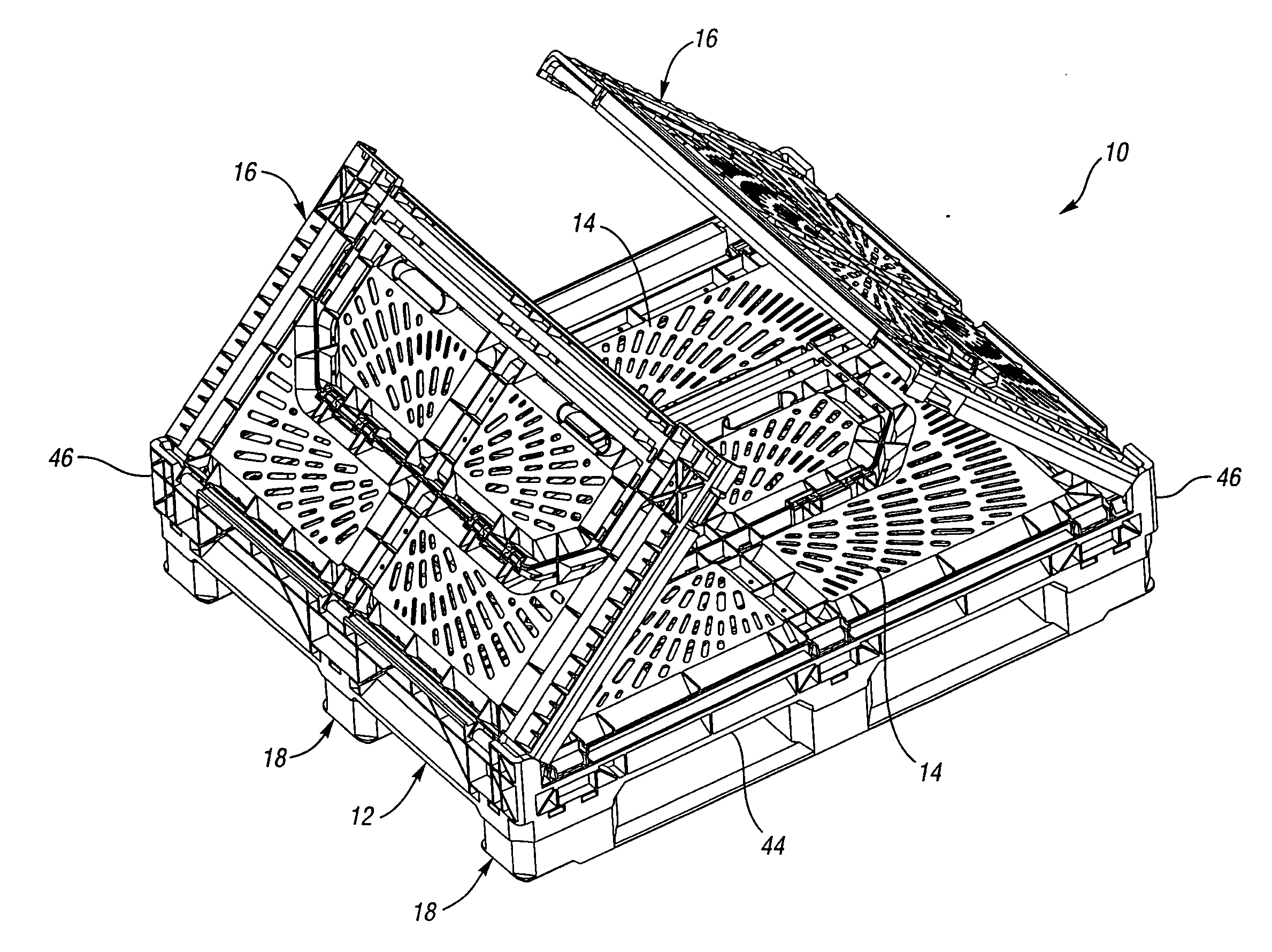
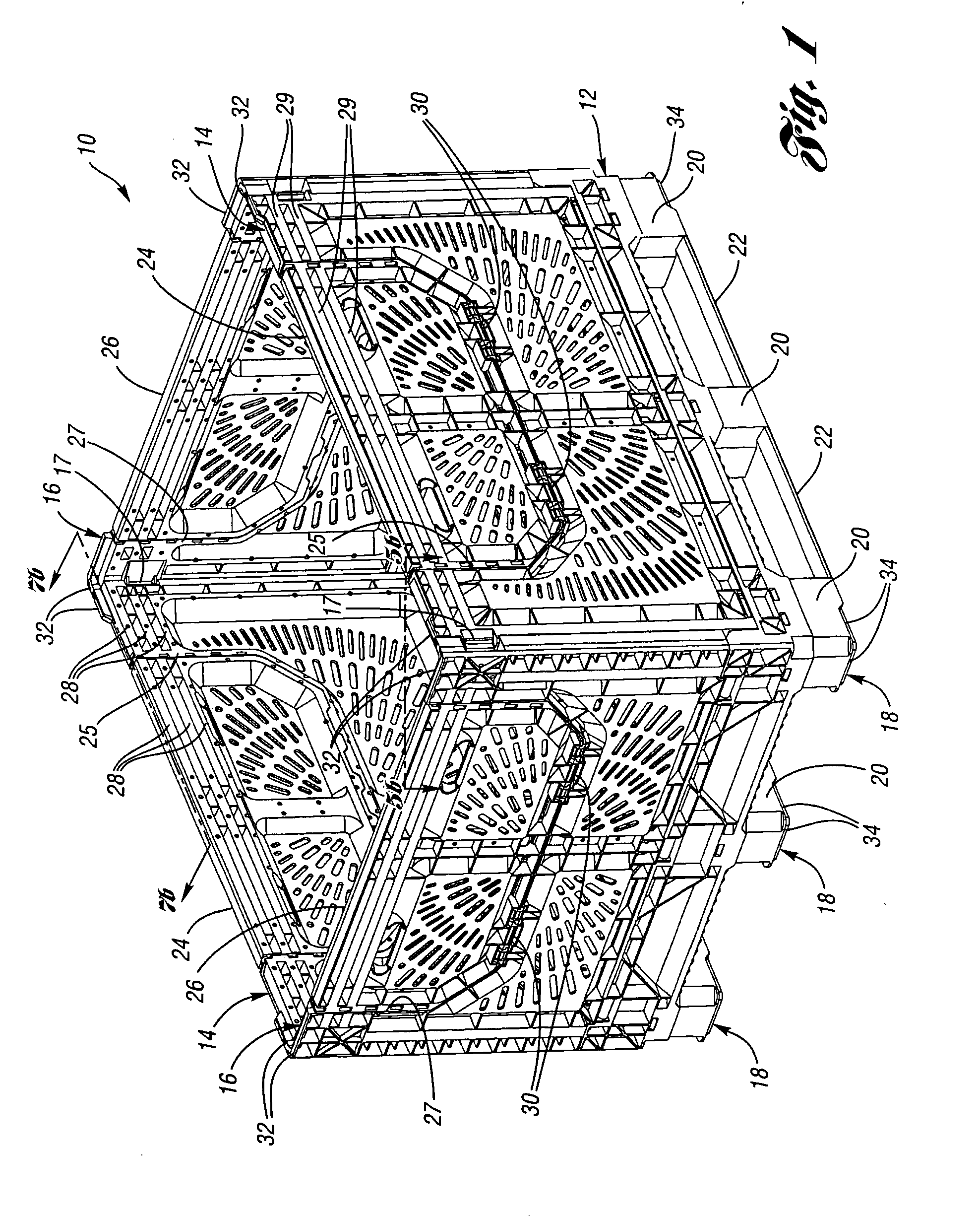
[0037] A pallet or field bin 10 according to one embodiment of the present invention is shown in FIG. 1. The bin 10 includes a base 12 and a pair of opposed side walls 14 extending upwardly from side edges of the base 12. End walls 16 extend upwardly from end edges of the base 12 and are releasably connected to the side walls 14 by latches 17.

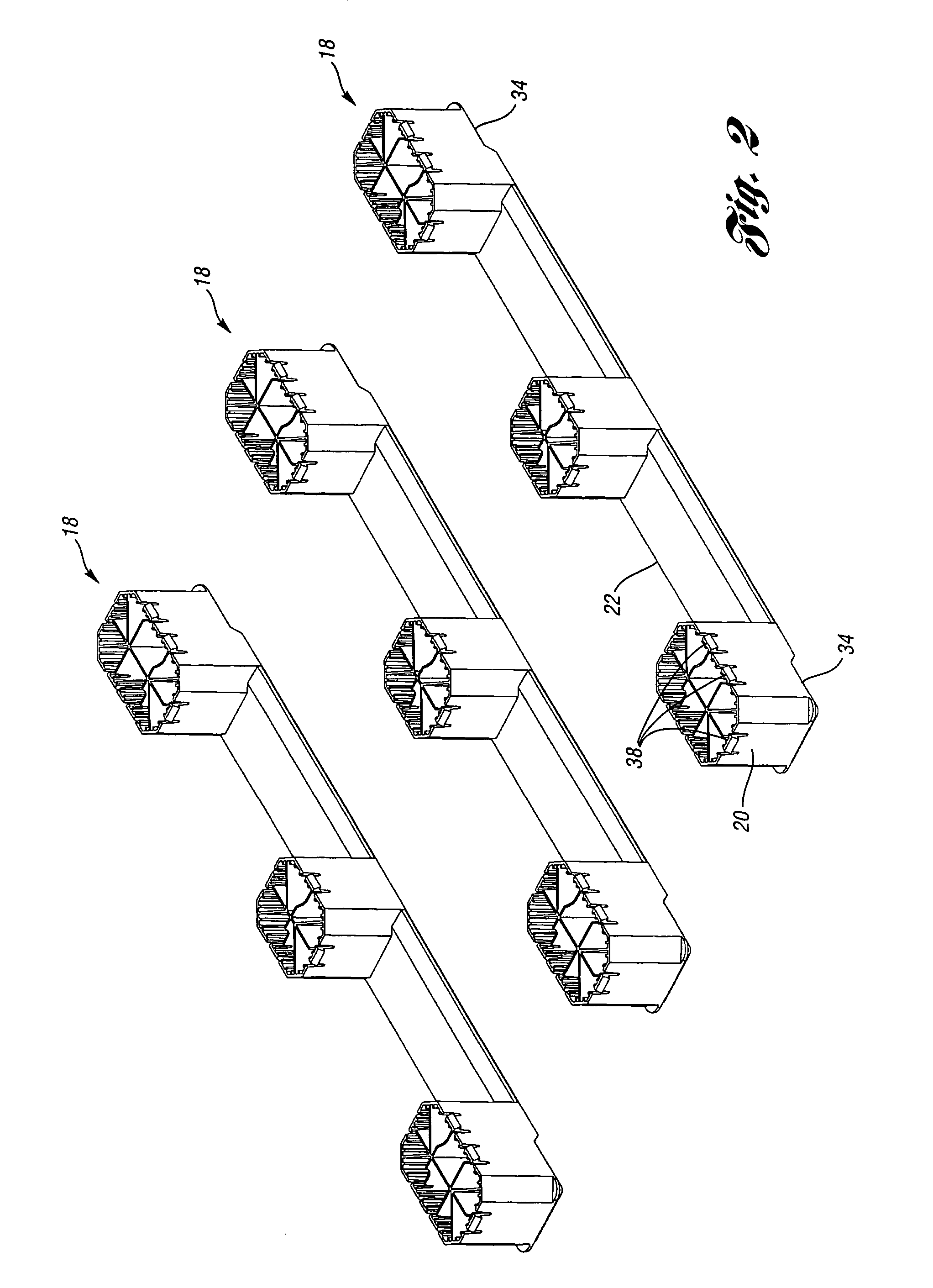
[0038] A plurality (three in this embodiment, although more or fewer could be used) of supports 18 are snap fit into the bottom of the base 12. Each support 18 includes a plurality (three in this embodiment, although more or fewer could be used) of columns 20 between which extends runners 22. The columns 20 and runners 22 are integrally molded together as a single unitary construction.

[0039] Each side wall 14 includes a drop wall or drop door 24 hingeably connected to the side wall 14 in an upwardly opening cutout 25 in the side wall 14. Similarly, each end wall 16 includes an upwardly opening cutout 27 into which is hingeably connected a dro...


PUM


Abstract

A pallet includes a plurality of supports supporting a floor. The supports each include a plurality of columns integrally-molded with at least one runner and snap-fit to the floor. At least one wall is moveable between an upright position and a collapsed position on the floor. A hinge connecting the wall to the base includes a first axis and a second axis offset by the first axis. The hinge is locked when the wall is in the upright position to prevent rotation about the second axis but permit rotation about the first axis. A hinge assembly connects a door to the wall and includes a first hinge pin and a second hinge pin. The hinge assembly permits the door to open completely relative to the wall to a position at least substantially parallel to and adjacent the wall.

Description

BACKGROUND OF THE INVENTION [0001] The present invention relates generally to pallets, and more particularly to a field bin. A field bin is generally a pallet with upstanding walls. Thus, some of these features are applicable to pallets, containers and to collapsible containers independently. [0002] There are numerous considerations in the design of a pallet or field bin. In addition to the acquisition costs, there are several costs in using and maintaining a field bin, including the cost of shipping, periodic cleaning, and repairs. [0003] Making the field bin collapsible can reduce shipping costs. Minimizing the height of the collapsed field bin reduces the cost of shipping the field bin when empty. Decreasing the weight of the container also decreases shipping costs. [0004] Damage to the field bin is largely incurred from the handling of the field bin with fork trucks. The runners, columns and base have direct contact with the blades and are therefore subject to the most abuse. Th...

Claims


Application Information

Patent Timeline
Patent Type & Authority Applications(United States)
IPC IPC(8): B65D19/00
CPCB65D19/18B65D2519/0099B65D2519/00069B65D2519/00104B65D2519/00174B65D2519/00273B65D2519/00288B65D2519/00318B65D2519/00333B65D2519/00407B65D2519/00412B65D2519/00422B65D2519/00502B65D2519/00522B65D2519/00567B65D2519/00587B65D2519/00651B65D2519/008B65D2519/00805B65D2519/00905B65D2519/0096B65D2519/00975B65D2519/00034B65D11/1833B65D21/0215B65D25/005B65D2519/00656E05D3/12
Inventor APPS, WILLIAM P.
Owner REHRIG PACIFIC CO INC
Why Eureka
Try Eureka