Image sensing device and control method therefor

a technology of image sensing and control method, which is applied in the direction of instruments, television systems, and television system scanning details, etc., can solve the problems of incorrect signal output, inability to output signals, and time shift between the top part of the screen and the bottom part of the screen time,

Inactive Publication Date: 2006-11-23
CANON KK
View PDF9 Cites 46 Cited by
  • Summary
  • Abstract
  • Description
  • Claims
  • Application Information

AI Technical Summary

Benefits of technology

[0019] According to the present invention, the foregoing object is attained by providing an image sensing apparatus comprising: a plurality of pixels arranged two dimensionally, each pixel containing a photoelectric converter that outputs a photoelectrically converted signal in response to a quantity of received light; an output unit containing a clamping circuit; a signal supply circuit that outputs a reference signal to the clamping circuit; a control unit that controls to clamp the reference signal prior to outputting the photoelectrically converted signal from the pixel to the clamping circuit, output the photoelectrically converted signal to the clamping circuit, and then output a noise signal from the pixel to the clamping circuit; and a differential circuit that subtracts the noise signal from the photoelectrically converted signal processed by the clamping circuit.
[0020] According to the present invention, the foregoing object is also attained by providing an image sensing apparatus capable of being driven by multiple scan methods including a first scan method and a second scan method, the image sensing apparatus comprising: a plurality of pixels arranged two dimensionally, each pixel containing a photoelectric converter that outputs a photoelectrically converted signal in response to a quantity of received light; an output unit containing a clamping circuit; a signal supply circuit that outputs a reference signal to the clamping circuit; a control unit that with a first scan method clamps a noise signal from the pixels with the clamping circuit and then outputs the photoelectrically converted signal to the clamping circuit, and with a second scan method controls to clamp the reference signal prior to outputting the photoelectrically converted signal from the pixel to the clamping circuit, output the photoelectrically converted signal to the clamping circuit, and then output a noise signal from the pixel to the clamping circuit; and a differential circuit that subtracts the noise signal from the photoelectrically converted signal processed by the clamping circuit.
[0021] Further, the foregoing object is also attained by providing a control method for an image sensing apparatus comprising a plurality of pixels arranged two dimensionally, each pixel containing a photoelectric converter that outputs a photoelectrically converted signal in response to a quantity of received light, an output unit containing a clamping circuit, and a signal supply circuit that outputs a reference signal to the clamping circuit, the method comprising: clamping the reference signal prior to outputting the photoelectrically converted signal from the pixel to the clamping circuit; outputting the photoelectrically converted signal to the clamping circuit; outputting a noise signal from the pixel to the clamping circuit; and subtracting the noise signal from the photoelectrically converted signal processed by the clamping circuit.

Problems solved by technology

A problem with the rolling electronic shutter shown in FIG. 12 is that the charge accumulation timing shifts between the top part of the screen and the bottom part of the screen time by the length of time required to scan the screen.
This not only makes it impossible to output the signals of the pixels of a part of the line n, but the remaining signals of the line n are also added to the signals of line n+1, leading to the wrong signals being output as the signals of the line n+1.
As a result, it is not possible to realize a sequence of operations in which the noise signal is output and then the light signal is output after the noise signal is clamped during readout of the light signal.

Method used


Image

  • Image sensing device and control method therefor
  • Image sensing device and control method therefor
  • Image sensing device and control method therefor

Examples


Embodiment Construction

[0039] A preferred embodiment of the present invention will now be described in detail in accordance with the accompanying drawings.

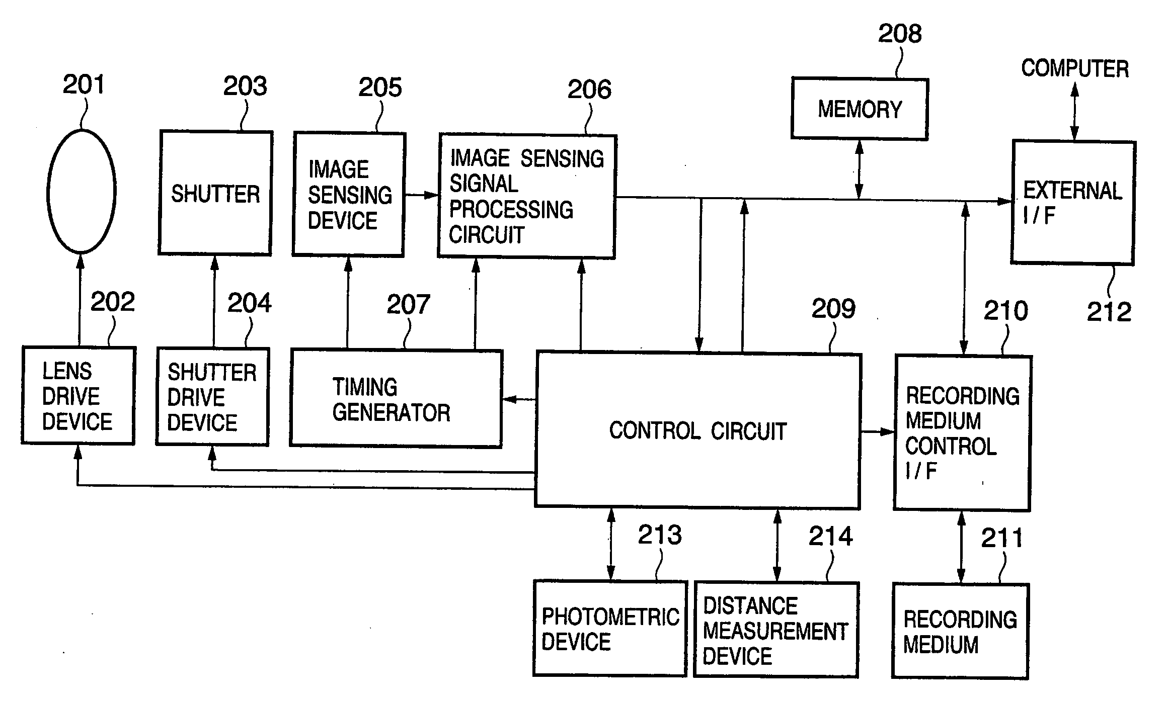
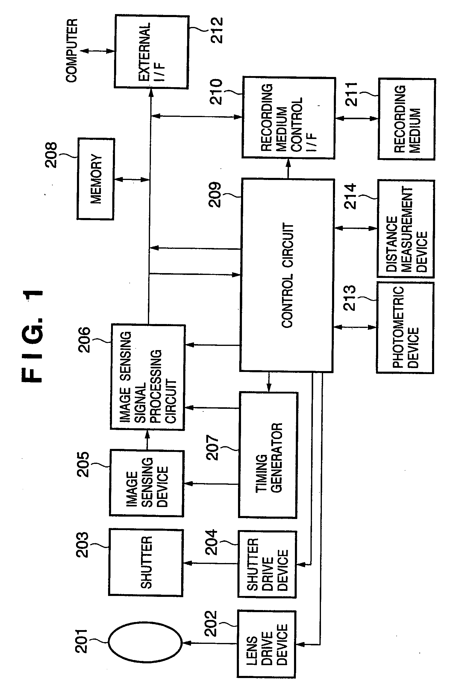
[0040]FIG. 1 is a block diagram showing the schematic structure of an image sensing apparatus of an embodiment of the present invention.

[0041] In FIG. 1, reference numeral 201 designates a lens unit for focusing an optical image of an object on an image sensing device 205, with lens zoom, focus and aperture control performed by a lens drive device 202. Reference numeral 203 designates a shutter, which is controlled by a shutter drive device 204. Reference numeral 205 designates the image sensing device that converts the optical image of the object focused by the lens unit 201 into an electrical image signal. Reference numeral 206 designates an image sensing signal processing circuit with the capability to amplify the image signal output from the image sensing device 205, to perform analog-to-digital (A / D) conversion on the image signal, and to carry o...


PUM


Abstract

An image sensing apparatus has a plurality of pixels arranged two dimensionally, each pixel containing a photoelectric converter that outputs a photoelectrically converted signal in response to a quantity of received light, an output unit containing a clamping circuit, a signal supply circuit that outputs a reference signal to the clamping circuit, a control unit that controls to clamp the reference signal prior to outputting the photoelectrically converted signal from the pixel to the clamping circuit, output the photoelectrically converted signal to the clamping circuit, and then output a noise signal from the pixel to the clamping circuit, and a differential circuit that subtracts the noise signal from the photoelectrically converted signal processed by the clamping circuit.

Description

FIELD OF THE INVENTION [0001] The present invention relates to an image sensing device that senses an object image using a photoelectric converter and a control method therefor. BACKGROUND OF THE INVENTION [0002] Conventionally, implementing an electronic shutter operation by executing a reset scan by pixel or by line to remove unneeded charges accumulated at the pixels and then carrying out a scan by pixel or by line to output the signal charge after a predetermined period of time has elapsed for each pixel or for each line is known. [0003] A description is now given of an electronic shutter operation in an image sensing apparatus that uses an image sensing device that employs a conventional XY address-type scan method. Specifically, using FIG. 11 and FIG. 12, a description is given of the structure of the conventional image sensing device and the drive method called rolling electronic shutter operation among the electronic shutter operations. [0004]FIG. 11 is a schematic diagram s...

Claims


Application Information

Patent Timeline
Patent Type & Authority Applications(United States)
IPC IPC(8): H04N5/335H04N5/357H04N5/363H04N5/369H04N5/374H04N5/378
CPCH04N5/3532H04N5/365H04N5/3575H04N25/531H04N25/616H04N25/67
Inventor KISHI, TAKAFUMI
Owner CANON KK
Why Eureka
Try Eureka