Method and apparatus for fusion splicing optical fibers

a technology of optical fibers and fusion splicing, applied in the field of preparation of optical fibers, can solve the problems unreliable splicing, and inability to meet the needs of optical fiber splicing,

Inactive Publication Date: 2006-11-23
3SAE TECH
View PDF36 Cites 33 Cited by
  • Summary
  • Abstract
  • Description
  • Claims
  • Application Information

AI Technical Summary

Problems solved by technology

In addition, the need to splice optical fibers also arises when an existing length of fiber breaks and must be repaired, or when an apparatus such as an amplifier must be incorporated into a length of fiber.
Mechanical splicing, however, produces splices that are often unreliable, both in terms of physical connection and optical performance, and is therefore not appropriate and / or effective in many applications.
These environments present two main problems when an optical fiber breaks and must be repaired.
First, because of the small spaces in which the optical fibers reside, it is impractical or impossible to use the relatively large and bulky fusion splicing equipment that is currently commercially available to repair breaks in fibers in situ.
Second, combustible vapors are often present in many of these environments, thereby making it prohibitively dangerous to use an electrical arc to fusion splice two fiber ends without removing the fiber portions from the environment.
As a result, inconvenient and often difficult measures must be taken to repair optical fibers in these environments.
As will be appreciated, this process is logistically difficult and requires a significant amount of fiber slack.
Another environment that is both space constrained and hazardous is today's modern aircraft, which typically include significantly more optical fiber than ever before due to the prevalence of optical sensors and the need for high speed data transfer, security and reliability.
The optical fiber is typically routed throughout the aircraft and can be difficult to reach when maintenance is required.
However, as described above, mechanical splicing is not sufficiently reliable, and, due to the presence of jet fuel, in situ fusion splicing is extremely dangerous.

Method used


Image

  • Method and apparatus for fusion splicing optical fibers
  • Method and apparatus for fusion splicing optical fibers
  • Method and apparatus for fusion splicing optical fibers

Examples


Embodiment Construction

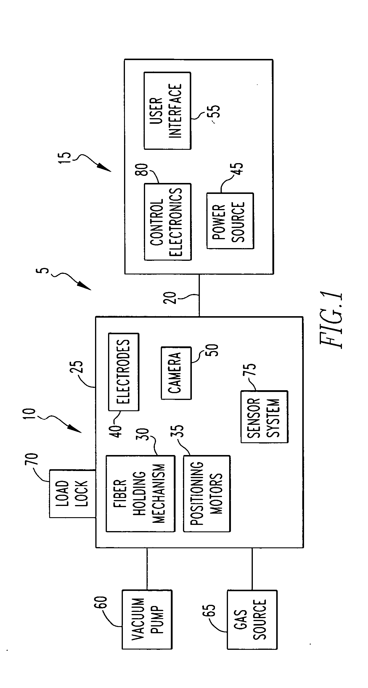
[0020]FIG. 1 is a block diagram of a fusion splicing apparatus 5 according to one embodiment of the present invention. As seen in FIG. 1, the fusion splicing apparatus 5 includes a splice head 10 and support hardware 15 that are connected to one another by cable assembly 20. Fusion splicing apparatus 5 is particularly well adapted for use in space constrained and / or hazardous environments because, as described in detail below, the splice head 10 (which includes the components for generating the electrical splicing arc) is physically separated from the support hardware 15, and the splice head 10 is isolated from the surrounding environment.

[0021] Splice head 10 includes an airtight enclosure 25 made of a material such as, without limitation, metal or plastic. Airtight enclosure 25 may take on any of a number of shapes, such as, without limitation, a rectangular, square or spherical shape. Splice head 10 is provided with a fiber holding mechanism 30 for holding the ends of the optica...


PUM


Abstract

An apparatus for fusion splicing optical fibers includes an airtight enclosure, a vacuum pump for evacuating the enclosure, first and second electrodes positioned within the enclosure, and a power source separate from an external to the enclosure for applying a voltage to the first electrode for generating an arc between the electrodes that is used to splice the first and second optical fiber portions together. Also, a method of fusion splicing optical fibers includes receiving first and second fiber portions within an airtight enclosure, evacuating the airtight enclosure, and applying a voltage to a first electrode within the enclosure from a source located separate from and external to the enclosure to cause the generation of an arc between the first electrode and a second electrode within the enclosure that is used to splice the first and second optical fiber portions together.

Description

CROSS-REFERENCE TO RELATED APPLICATION [0001] The present application claims the benefit of U.S. Provisional Application No. 60 / 682,105, entitled “Method and Apparatus for Fusion Splicing Optical Fibers,” which was filed on May 18, 2005.BACKGROUND OF THE INVENTION [0002] 1. Field of the Invention [0003] The present invention relates to the preparation of optical fibers, and in particular to a method and apparatus for fusion splicing optical fibers. [0004] 2. Description of the Prior Art [0005] Fiber optic cables are widely used in modern optical devices and optical communications systems. Optical fibers are strands of glass fiber processed so that light beams transmitted through the glass fiber are subject to total internal reflection wherein a large fraction of the incident intensity of light directed into the fiber is received at the other end of the fiber. Optical fibers typically consist of a cylindrical core made of a first glass that is position inside a cylindrical casing mad...

Claims


Application Information

Patent Timeline
Patent Type & Authority Applications(United States)
IPC IPC(8): G02B6/255
CPCG02B6/2553G02B6/2551
Inventor WILEY, ROBERT G.GRASSO, DONALDVALLE, STEVEN A.RIVERA, ROBERTO A.MEITZLER, JAREDTROUTMAN, CLYDE
Owner 3SAE TECH
Why Eureka
Try Eureka