Knee prosthesis

a prosthesis and femur technology, applied in the field of knee prosthesis, can solve the problems of supra-condylar fracture of the femur, surgeon with a problem, and inability to accurately match up the bony landmarks

Active Publication Date: 2006-11-23
MCMINN DEREK JAMES WALLACE
View PDF9 Cites 83 Cited by
  • Summary
  • Abstract
  • Description
  • Claims
  • Application Information

AI Technical Summary

Benefits of technology

[0009] Preferably the part of the femoral flange is angled by a value in the range of approximately 3° to approximately 20°, and more preferably by 10°, relative to said plane. Desirably an internal surface of the femoral flange extending away fr

Problems solved by technology

One problem with such total knee replacement relates to the matching of the interior surface of the femoral component of the implant with the resected distal anterior surfaces of the femur. FIG. 1 shows a femoral bone, and from this it can be seen that the lateral femoral condyle (LFC) is longer than the medial femoral condyle (MFC) and that the condyles blend with the shaft of the femur in a different way on each side.
This presents the surgeon with a problem.
This provides a p

Method used


Image

  • Knee prosthesis
  • Knee prosthesis
  • Knee prosthesis

Examples


Embodiment Construction

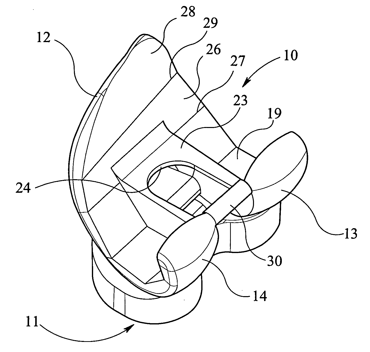
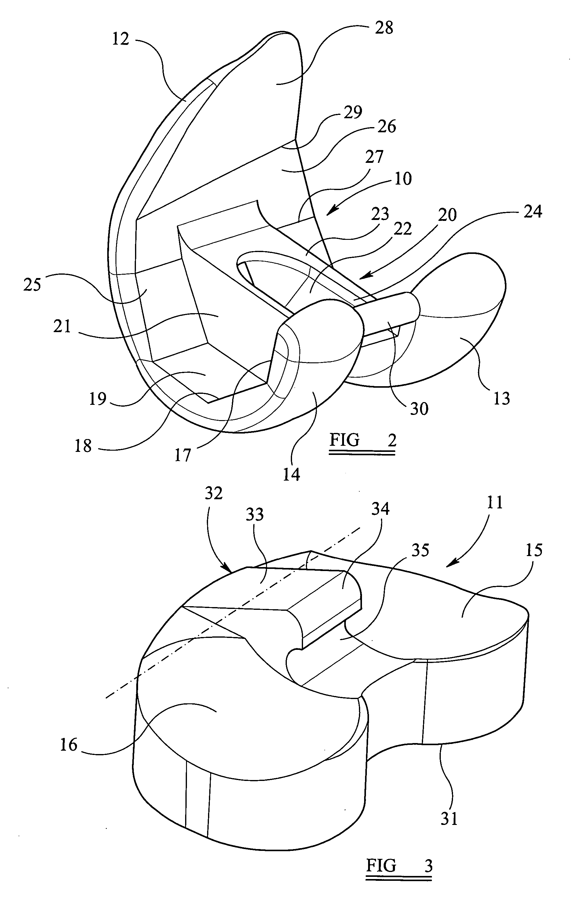
[0021] The invention relates to a femoral component of a knee prosthesis, the femoral component being shown alone in FIG. 2.

[0022] As is well known, a knee prosthesis generally comprises a femoral component, a tibial component, and a meniscal or bearing component. Generally the femoral and tibial components are of metal with the bearing component being of plastics material such as polyethylene and fitting between the femoral and tibial components. In the accompanying drawings the tibial component is not shown, but it is to be understood that this would generally be of conventional form, such as in U.S. Pat. Nos. 5,387,240 and 5,658,342 having a flat upper surface in use, on which the flat lower surface of the bearing component engages, and a depending lower fixing stem. In FIGS. 2 and 3, the femoral component is indicated by the numeral 10 and the bearing component is indicated by the numeral 11.

[0023] The knee replacement device shown in the drawings is of bicondylar form, with t...


PUM


Abstract

A femoral component of a knee prosthesis comprises a femoral flange from an inner end of which extend lateral and medial condylar parts which are interconnected by a box-like bridging part at an intercondylar groove. The interior surface of the femoral component has six discrete flat sections, with the sixth flat section which extends to a free end of the femoral component being angled relative to a plane normal to the third flat section and to the length of the intercondylar groove. Also disclosed is a trial femoral component and a method of use thereof to prepare a femur for the fitting of the femoral component of the prosthesis.

Description

CROSS REFERENCE TO RELATED APPLICATION [0001] This application relates to and claims priority to corresponding Great Britain Patent Application No. 0510194.4, which was filed on May 19, 2005, and which is incorporated by reference herein. BACKGROUND OF THE INVENTION [0002] 1. Field of the Invention [0003] This invention relates to a knee prosthesis for fitting to a patient as a replacement knee joint. [0004] 2. Related Art [0005] Modern total knee replacement involves the resurfacing of the femoral condyles with a metallic component, roughly approximating to the shape of the anatomical femoral condyles, and resurfacing the tibial plateau with a polyethylene component having a metallic base plate. [0006] One problem with such total knee replacement relates to the matching of the interior surface of the femoral component of the implant with the resected distal anterior surfaces of the femur. FIG. 1 shows a femoral bone, and from this it can be seen that the lateral femoral condyle (LF...

Claims


Application Information

Patent Timeline
IPC IPC(8): A61F2/38A61B17/15
CPCA61F2/3859A61B17/155A61F2/4684
Inventor MCMINN, DEREK JAMES WALLACE
Owner MCMINN DEREK JAMES WALLACE
Why Eureka
Try Eureka