
Fixation device for the talus

a technology for fixing devices and talus, which is applied in the field of talus bone fixation devices, can solve the problems of difficult repositioning of the bone correctly, reduced and fixed talus fractures, and difficult talus fractures, etc., and achieves the effect of reducing and fixing

Inactive Publication Date: 2006-10-19
BIOMET CV
View PDF14 Cites 67 Cited by
  • Summary
  • Abstract
  • Description
  • Claims
  • Application Information

AI Technical Summary

Benefits of technology

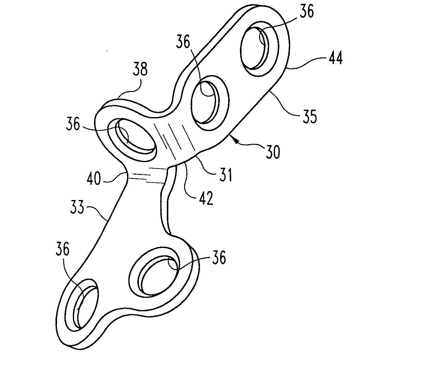
"The present invention provides a talus fixation device that is low-profile and can be attached across the lateral and dorsal aspects of the talus. The device includes a plate with lower and upper wings that can be in simultaneous contact with the talus. The plate has a first bend region that allows the lower and upper wings to be in uniform contact with the talus. The plate also has screw holes for bone engaging fasteners. The upper wing has a second bend region that allows it to conform to the contour of the dorsal aspect of the talus. The device can be used to reduce and fix fractures of the talus, and it provides multiple degrees of freedom for screw fixation. The device helps retain bone fragments and ensures proper reconstruction of the fractured talus."

Problems solved by technology

Such injuries often occur in a motor vehicle accident in which the ankle is hyper-flexed by the brake pedal.
On rare occasions, talar neck fractures involve displacement of the bone fragments, which are significant medical emergencies because of the risk of avascular necrosis for a talus bone with already limited vascularization.
Fractures of the talus can be extremely significant, and even with good treatment can lead to numerous complications.
When the main fracture is fixed it is often difficult to reposition the bone correctly so that the foot is turned inward (a varus deformity).
Reduction and fixation of talar fractures has been limited to bone screws and pins.
However, where more severely comminuted fractures are involved, fixation and reduction using screws and pins is usually insufficient.

Method used


Image

  • Fixation device for the talus
  • Fixation device for the talus
  • Fixation device for the talus

Examples


Embodiment Construction

[0027] For the purposes of promoting an understanding of the principles of the invention, reference will now be made to the embodiments illustrated in the drawings and described in the following written specification. It is understood that no limitation to the scope of the invention is thereby intended. It is further understood that the present invention includes any alterations and modifications to the illustrated embodiments and includes further applications of the principles of the invention as would normally occur to one skilled in the art to which this invention pertains.

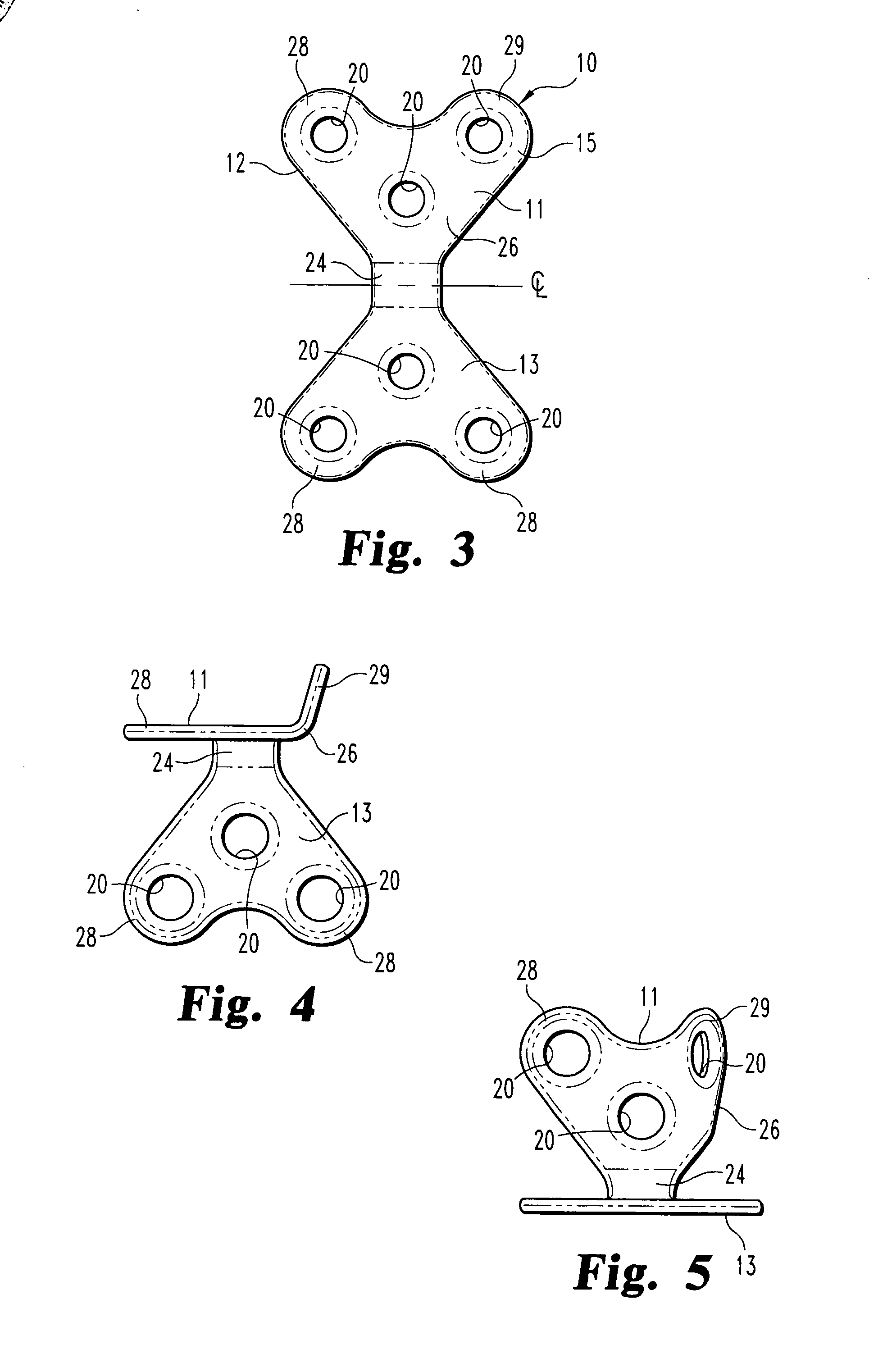
[0028] The present invention provides a fixation device 10 that is initially configured as a flat plate 11, as shown in FIG. 3. The plate has a minimal thickness, about 1.0 mm or less, to reduce the prominence of the plate above the talus. In the preferred embodiment, the plate is formed of a medical grade metal, such as a titanium alloy. Most preferably, the plate 11 is formed of the titanium alloy TI-6AL-4V....


PUM


Abstract

A fixation device for reduction and fixation of fractures of the talus bone of the foot includes a thin titanium alloy plate having a lower wing configured for attachment to the lateral aspect of the talus and an upper wing configured for attachment to the dorsal aspect of the talus. The plate includes a substantially perpendicular or right angle bend between the lower and upper wings. In one embodiment, each wing includes three screw holes arranged in a generally triangular pattern. Two holes on each plate are situated in tabs and the center of the plate has a reduced width so that the plate presents a minimal profile. One of the tabs on the upper wing is bent away from the lower wing at a pre-determined angle so that the wing conforms to the shape of the talus. In an alternative embodiment, the upper wing includes a step portion between the lower wing and the bent tab and carrying one screw hole. In this embodiment, the bent tab is generally elongated with one or two screw holes disposed along its length.

Description

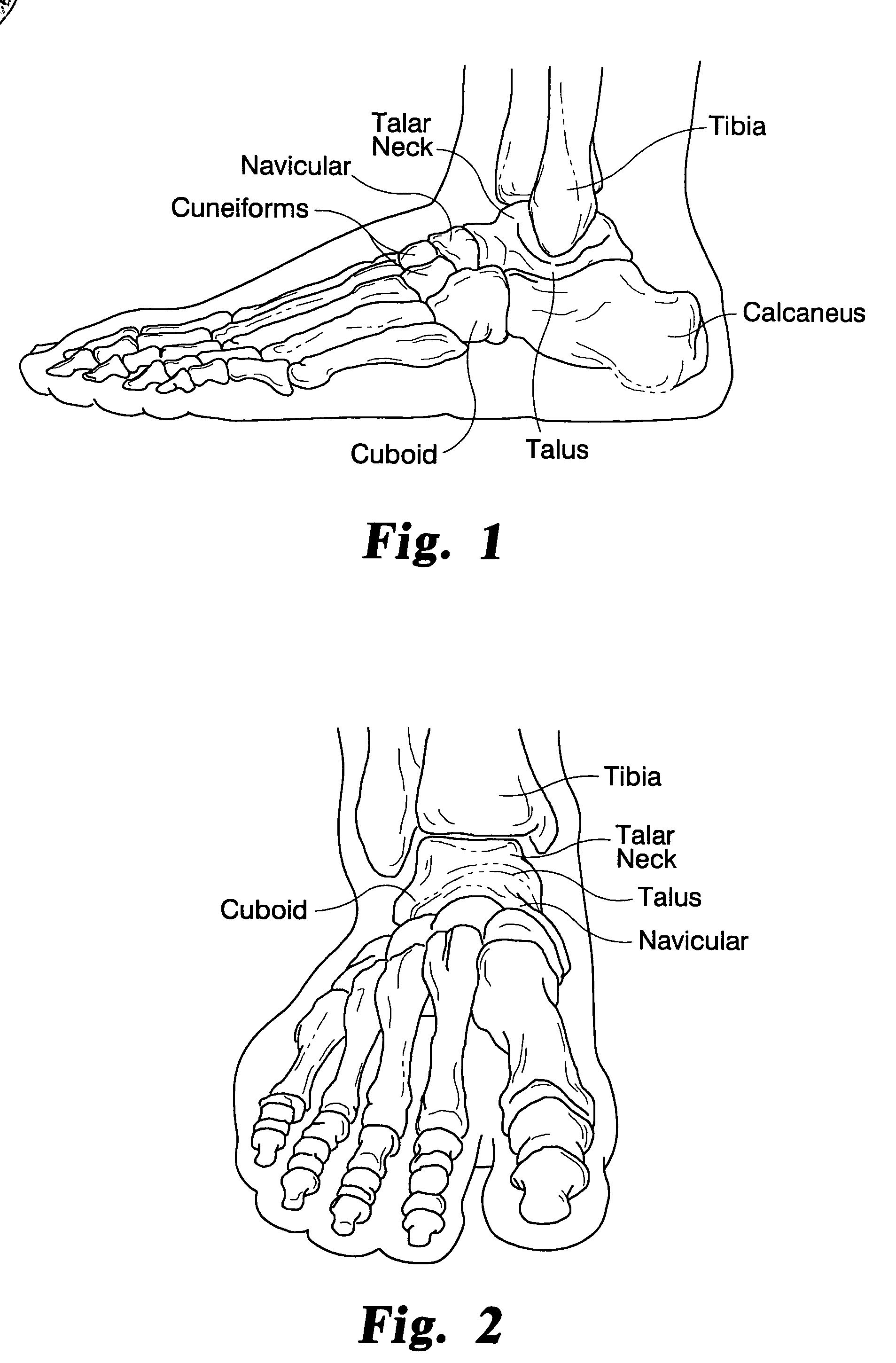
[0001] The present invention relates to fixation devices for the bones of the foot, and particularly for the talus bone. The invention is especially suitable for reducing fractures of the neck of the talus. [0002] The talus is a critical bone of the ankle joint. As shown in FIGS. 1-2, the talus connects the leg to the foot. In particular, the tibia articulates on talar dome (see FIG. 6) to produce the multiple degrees of freedom of movement of the ankle, including the upward and downward movement (dorsiflexion and plantarflexion). The talus also articulates on the calcaneous bone to produce the majority of the inward and outward movement (inversion and eversion) of the foot. [0003] Fractures of the talus typically involve either the talar neck or lateral process, or osteochondral fractures of the talar dome. Talar neck fractures are usually high-energy injuries involving hyperdorsiflexion of the ankle. Such injuries often occur in a motor vehicle accident in which the ankle is hyper...

Claims


Application Information

Patent Timeline
Patent Type & Authority Applications(United States)
IPC IPC(8): A61F2/30
CPCA61B17/8085A61B17/8061
Inventor SANDERS, ROYPRASAD, PRIYABREMER, CHRIS
Owner BIOMET CV
Learn More