Eureka AIR delivers breakthrough ideas for toughest innovation challenges, trusted by R&D personnel around the world.

Camera module and lens moving control device thereof

Inactive Publication Date: 2006-11-30
ASUSTEK COMPUTER INC
View PDF8 Cites 2 Cited by
  • Summary
  • Abstract
  • Description
  • Claims
  • Application Information

AI Technical Summary

Benefits of technology

[0011] It is therefore an object of the invention to provide a camera module and lens moving control device thereof. The above-mentioned disadvantages of the conve

Problems solved by technology

Owing that the elastic devices have to contact with lens components, a loud noise and resonant vibration is gener

Method used


Image

  • Camera module and lens moving control device thereof
  • Camera module and lens moving control device thereof
  • Camera module and lens moving control device thereof

Examples


Example

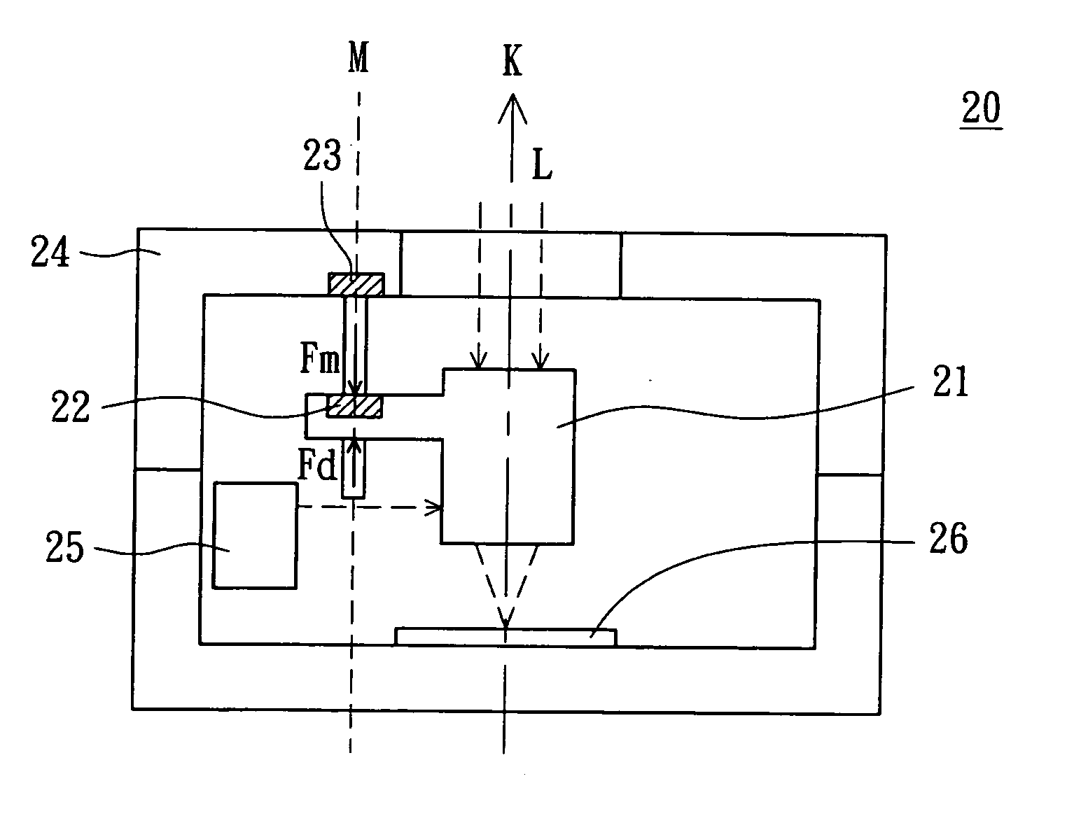
[0019] The invention uses a lens moving control device to provide a controlling force for lens moving in a camera module instead of the conventional contact-type spring mechanism. Besides, based on the same operation principles, the invention can be applied to optical lens modules in any type of digital camera, and mobile phone with digital camera function.

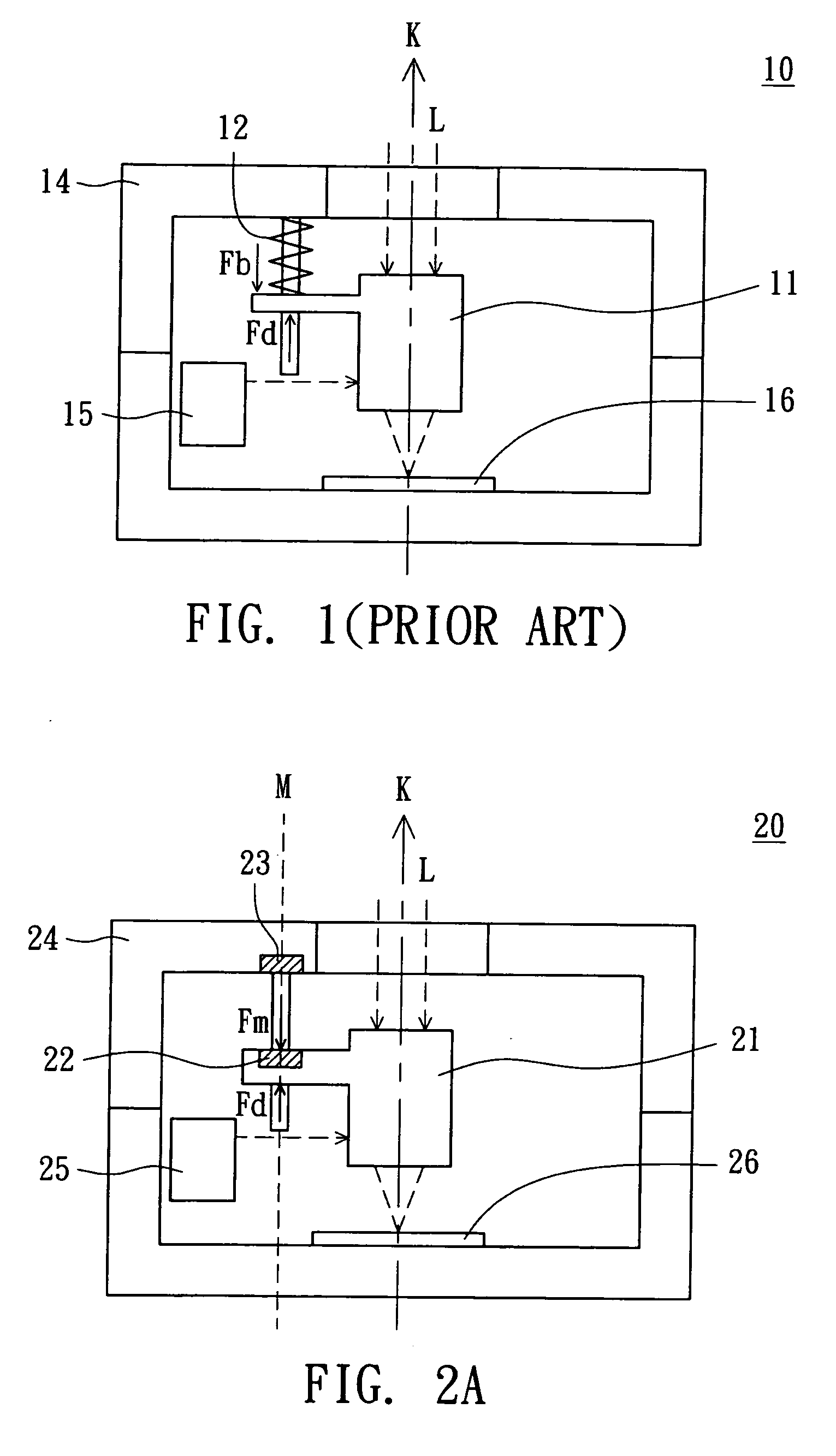
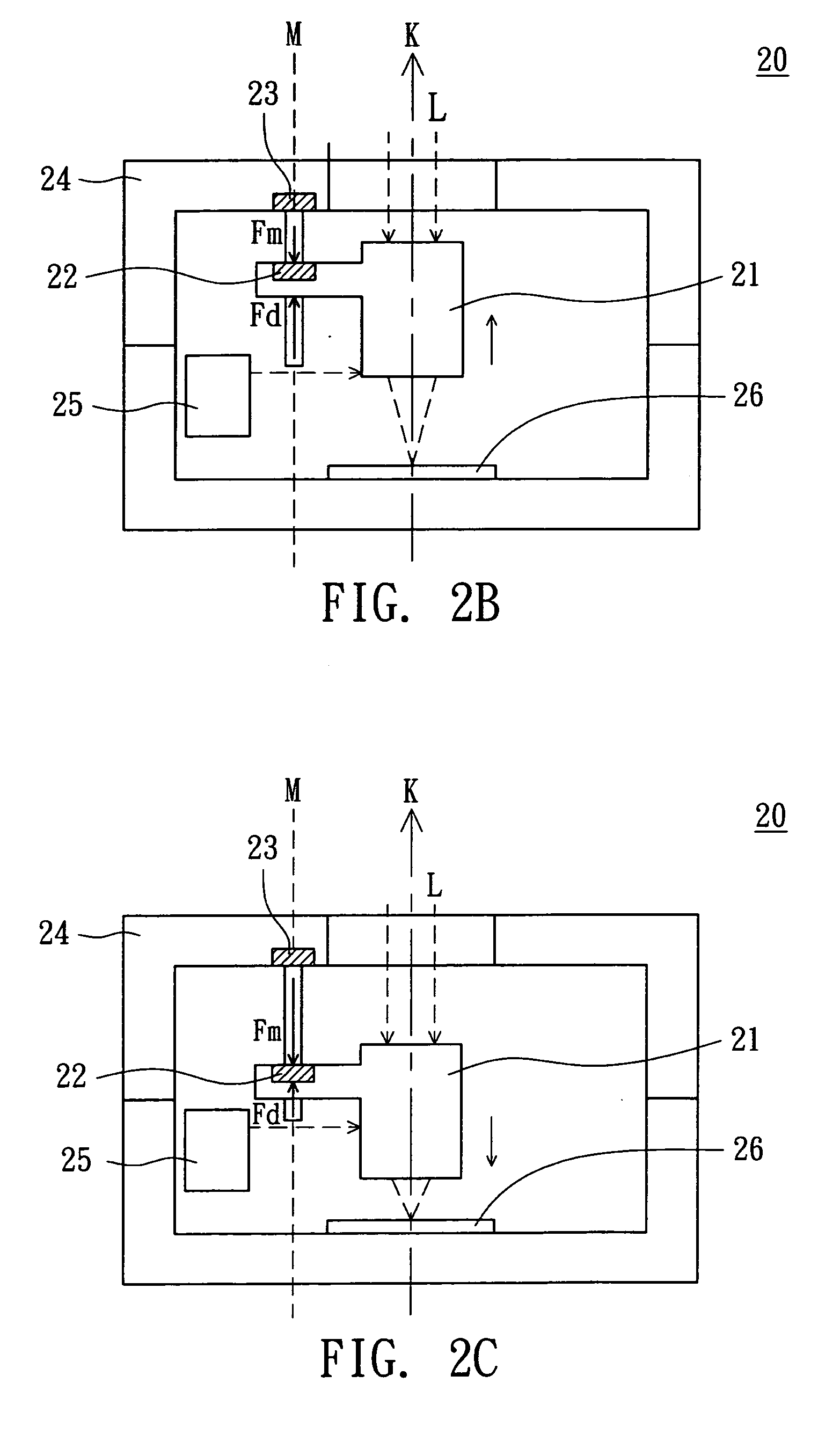
[0020] Referring to FIG. 2A, a cross-sectional view of a camera module according to a preferred embodiment of the invention is shown. The camera module 20, such as used in a mobile phone or a digital camera, includes a lens 21, a first magnetic device 22, a second magnetic device 23, an upper housing 24, an actuator 25 and a sensor 26. In the camera module 20, the actuator 25 generates a driving force Fd to move the lens 21 along an optical-axis direction K so that the light L incident into the lens 21 can be focused on the sensor 26. The first magnetic device 22 is embedded in the lens 21 while the second magnetic device 23 is e...


PUM


Abstract

A camera module includes a lens, an actuator, a first magnetic device and a second magnetic device. The actuator is for applying a driving force to move the lens. The first magnetic device is disposed on the lens. The second magnetic device is for incorporating with the first magnetic device to generate a controlling force. The controlling force is reverse to the driving force in direction. When the actuator applies the driving force to move the lens, the controlling force provided by the second magnetic device serves as a controlling force for the lens moving.

Description

[0001] This application claims the benefit of Taiwan application Serial No. 94117567, filed May 27, 2005, the subject matter of which is incorporated herein by reference. BACKGROUND OF THE INVENTION [0002] 1. Field of the Invention [0003] The invention relates in general to a camera module, and more particularly to a camera module using a controlling force to restore lens moving, and lens moving control device thereof. [0004] 2. Description of the Related Art [0005] In a camera module of a prior digital camera, the lens is driven to move by an actuator. In addition, the lens requires a controlling force to move back and forth so as to focus images on a sensor. [0006]FIG. 1 shows a cross-sectional view of a conventional camera module using a spring to generate the controlling force. In the camera module 10, the actuator 15 generates a driving force Fd to move the lens 11 along an optical-axis direction K, meanwhile the spring 12 generates a controlling force Fb to restore motion of t...

Claims


Application Information

Patent Timeline
IPC IPC(8): G03B13/18
CPCG03B13/18
Inventor CHEN, YUNG-CHUANLEE, YI-MINGCHEN, YEN-KUANG
Owner ASUSTEK COMPUTER INC
Why Eureka
Eureka Blog
Learn More