
Detecting wear through use of information-transmitting devices

a technology of information transmission device and wear detection, which is applied in the direction of brake disc, transportation and packaging, instruments, etc., can solve the problems of inability to scan (i.e., receive a signal from) the device, damage or missing of the information transmission device,

Inactive Publication Date: 2006-12-07
IBM CORP
View PDF22 Cites 71 Cited by
  • Summary
  • Abstract
  • Description
  • Claims
  • Application Information

AI Technical Summary

Benefits of technology

[0004] In one aspect, the present invention comprises a method of detecting wear through use of information-transmitting devices, comprising a step of providing at least one information-transmitting wireless device for each of on

Problems solved by technology

An information-transmitting device may become damaged or missing, due to item wear, and an RFID reader may therefore be unable to scan (i.e., receive a signal from) the device.

Method used


Image

  • Detecting wear through use of information-transmitting devices
  • Detecting wear through use of information-transmitting devices
  • Detecting wear through use of information-transmitting devices

Examples


Embodiment Construction

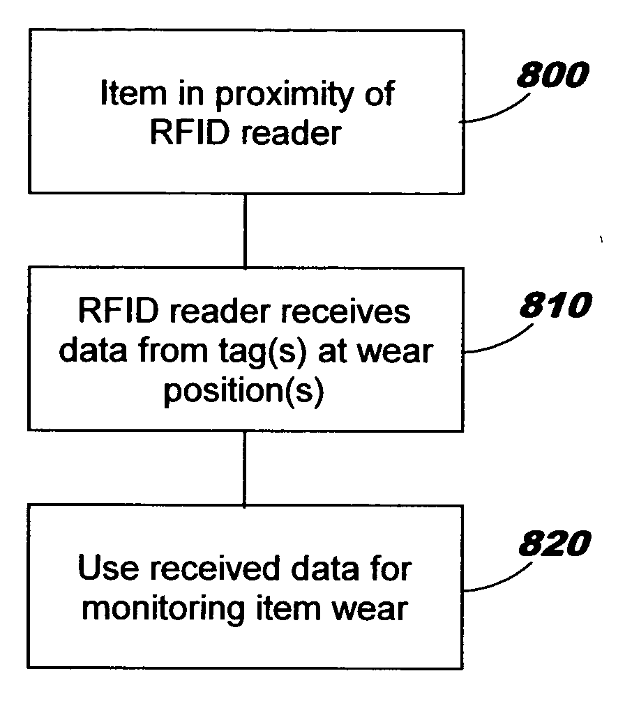
[0019] Embodiments of the present invention enable detecting (referred to herein equivalently as “measuring”) wear of items using information-transmitting tags. For example, the tags may be embedded or otherwise attached to an item; as another example, a tag might be placed in a receptacle of an item. Degree of wear may be measured. Wear patterns may be detected across one or more wear positions. Notifications pertaining to wear may be generated.

[0020] Through use of techniques disclosed herein, the time and skill it takes to routinely inspect items for degree of wear and / or proper wear patterns can be reduced. In addition, knowing when to replace items that wear, thereby improving safety and / or comfort, is facilitated. A wear pattern that does not fall within a threshold of an expected rate might indicate, for example, that the corresponding item is improperly installed or is defective.

[0021] RFID tags can be created using relatively inexpensive manufacturing techniques, and the ...


PUM


Abstract

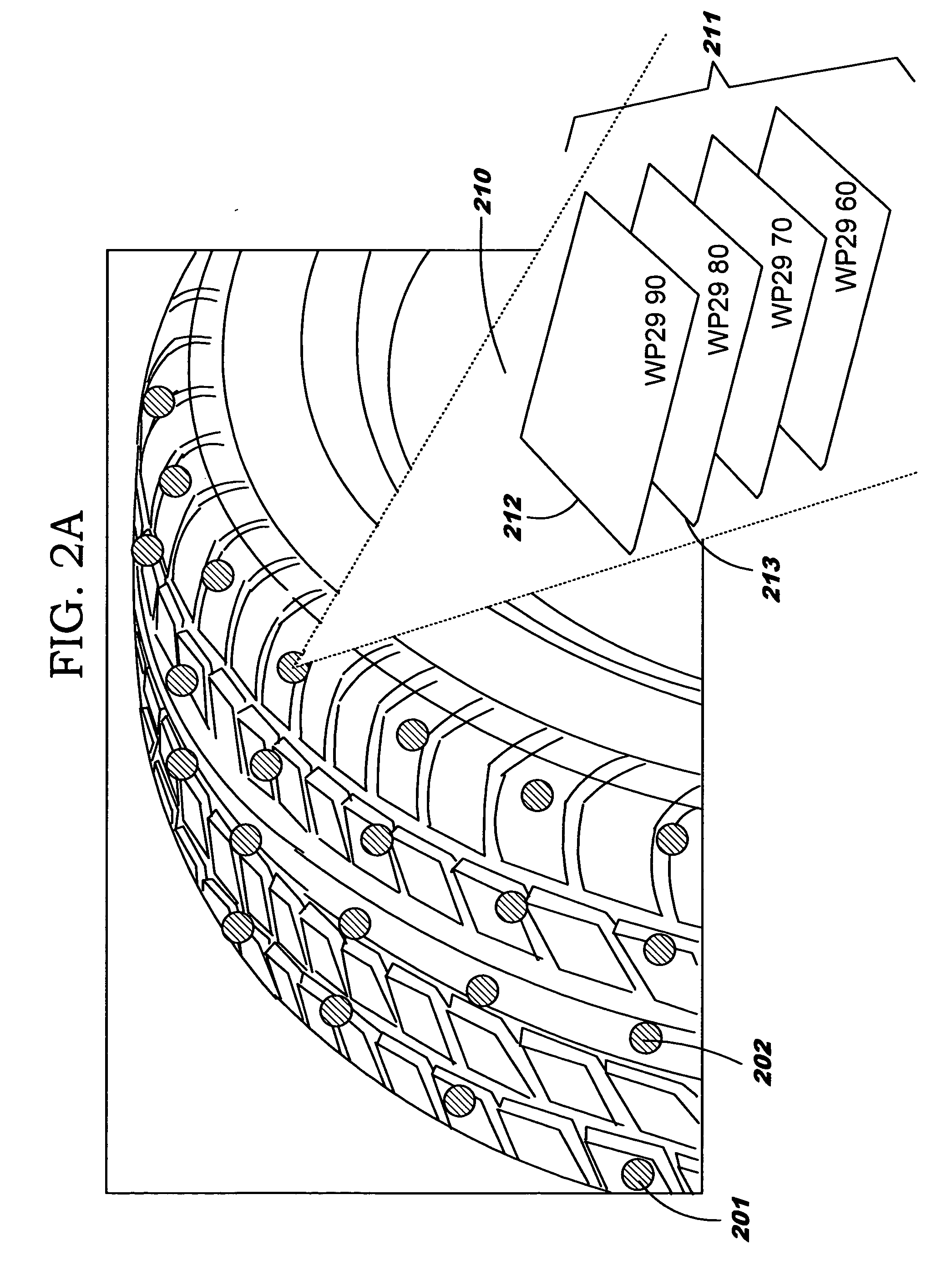
Detecting wear through use of information-transmitting devices. At least one information-transmitting wireless device is provided for each of one or more wear positions of an item, wherein each of the devices is adapted for transmitting information to a reader, such that each of the devices can transmit information usable for detecting wear of the item as the item wears. When using a plurality of devices for a particular wear position, the devices may be stacked or placed in a depth-wise, end-to-end arrangement. As another alternative, a single device having a plurality of separable areas may be provided for each of one or more wear positions. As yet another alternative, a single device may be provided for each of one or more wear positions such that its failure to transmit indicates wear at the corresponding wear position. An information-transmitting device may become damaged or missing, due to item wear, and an RFID reader may therefore be unable to scan (i.e.., receive data from) the device.

Description

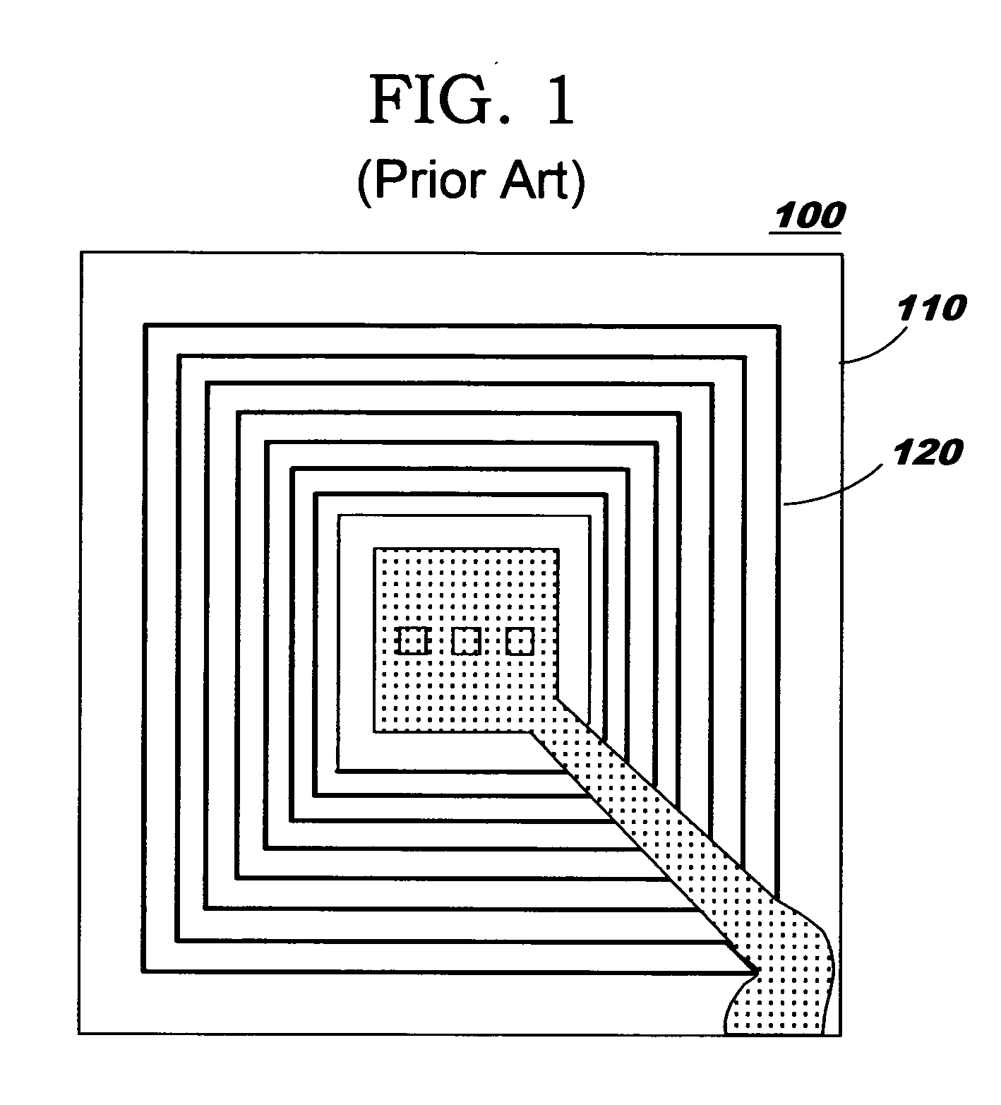
BACKGROUND OF THE INVENTION [0001] The present invention relates generally to information-transmitting devices (such as radio frequency identification, or “RFID”, tags), and more particularly, the use of such devices for detecting wear of items. [0002] Information-transmitting devices, such as those commonly referred to as RFID tags, may be used for labeling and tracking items of merchandise from manufacturing through distribution and retail sale. A typical RFID tag includes both passive elements (e.g., an antenna) and active elements (e.g., a read-write data memory, control circuitry, and a radio frequency transponder). RFID transmissions are, by definition, wireless. RFID tags are typically not self-powered, but may receive their power via capacitative coupling from an external radio frequency source. When brought into proximity with an RFID reader at a typical effective distance of about 1 centimeter to 5 meters (depending on the type of tag), the RFID tag receives sufficient pow...

Claims


Application Information

Patent Timeline
IPC IPC(8): G06F17/00G06F7/00
CPCB60C11/24F16D65/12F16D66/021
Inventor KARSTENS, CHRISTOPHER K.
Owner IBM CORP
Learn More