Flat panel display having non-evaporable getter material

a technology of getter material and flat panel display, which is applied in the direction of cathode ray tube/electron beam tube, electrical discharge tube, electrical apparatus, etc., can solve the problems of reducing the absorption efficiency of getter material, affecting the performance and lifetime of display, and affecting the performance of flat panel display performan

Inactive Publication Date: 2006-12-07
TSINGHUA UNIV +1
View PDF16 Cites 5 Cited by
  • Summary
  • Abstract
  • Description
  • Claims
  • Application Information

AI Technical Summary

Problems solved by technology

One problem with flat panel displays is that the internal components continuously outgas, which causes the performance of flat panel displays to degrade over time.
The former is not suitable for use in flat panel displays because of the possible short-circuit caused by evaporating metal film.
When non-evaporable getter materials are used, they are usually arranged in a corner of the flat panel device, but the conductance from the outgassing site to these getters are limited by the narrow space between the flat plates, causing reduction of the getters' absorption efficiency and in consequence the display's performance and lifetime.
There are also according solutions in which a separate space for containing getter materials is added to the device, but the structure thereof becomes complicated and the manufacture cost will be increased.

Method used


Image

  • Flat panel display having non-evaporable getter material
  • Flat panel display having non-evaporable getter material

Examples


first embodiment

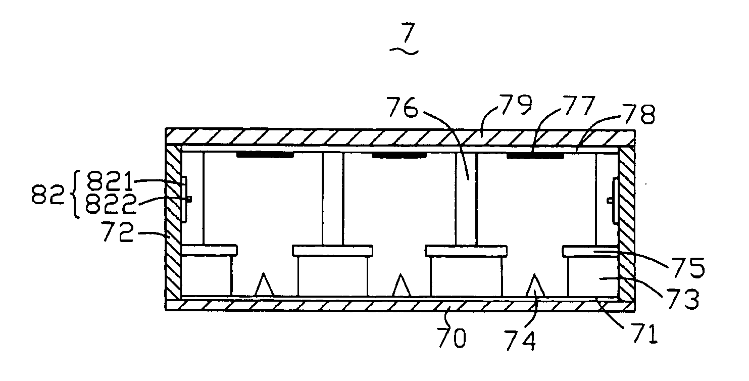
[0015] Referring to FIG. 1, a flat panel display 7 is shown in accordance with a The flat panel display 7 generally includes a front substrate 79 and a rear substrate 70 opposite thereto. The front substrate 79 is formed with an anode 78. The rear substrate 70 is formed with a cathode 71 facing the anode 78. Several sidewalls 72 are interposed between the front substrate 79 and the rear substrate 70. A plurality of getter devices 82 are arranged on the sidewalls 72. Thereby, a a substantial vacuum is maintained in the chamber between the front substrate 79 and the rear substrate 70.

[0016] In the illustrated embodiment, the rear substrate 70 is made of glass. The cathode 71 is an electrically conductive layer, and formed on a surface of the rear substrate 70 facing the anode 78. A plurality of emitters 74 are formed on the cathode 71, for emitting electrons. The emitters 74 can be composed of carbon nanotubes, diamond, diamond-like carbon (DLC), silicon, or of a tip-shaped metal mat...

second embodiment

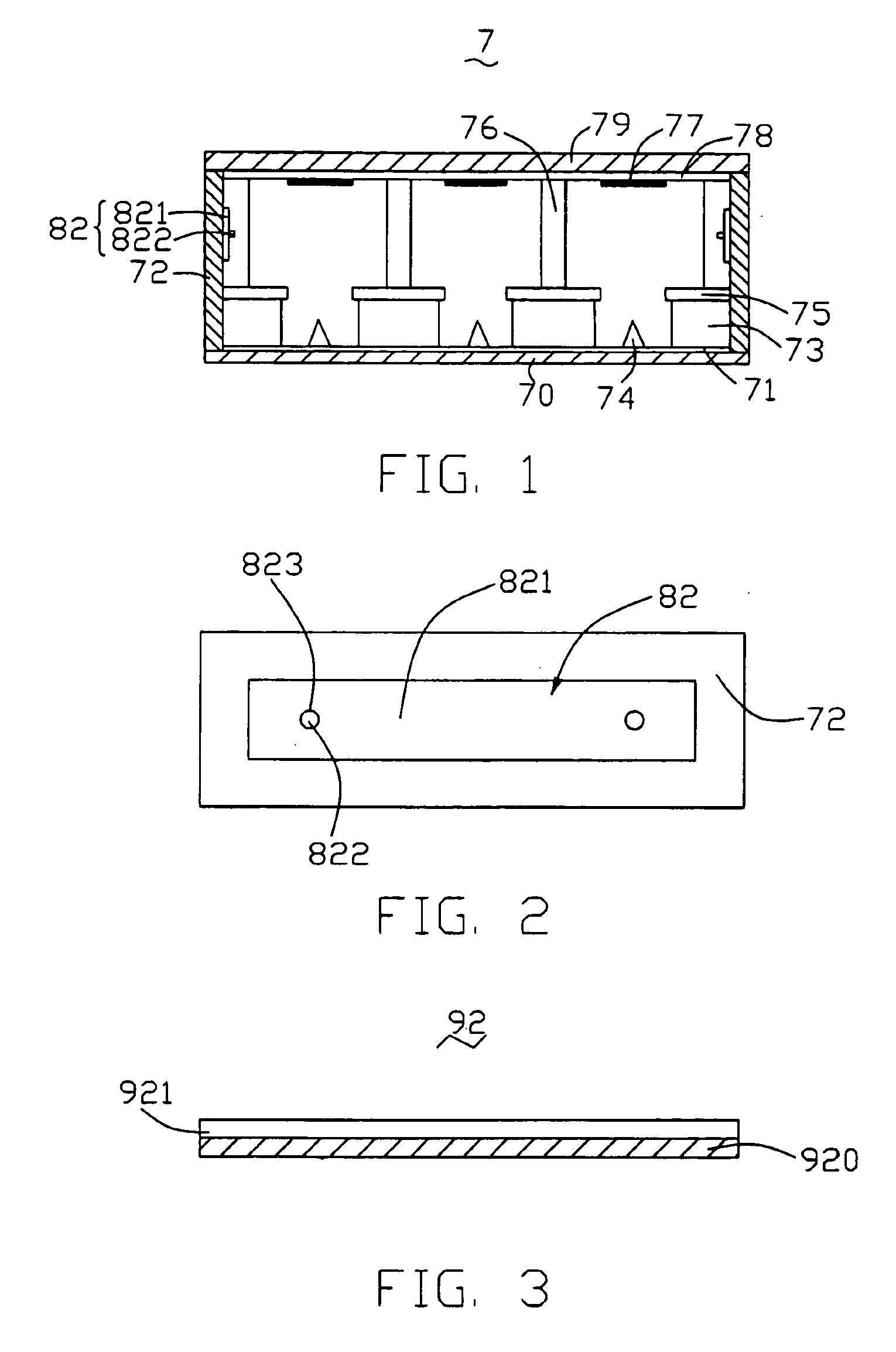
[0021] Referring to FIG. 3, another getter device 92 is shown as a replacement of the getter device 82. The getter device 92 includes a base 920 and a getter layer 921 formed thereon. The getter layer 921 is strip-shaped, and is comprised of non-evaporable getter materials. The getter layer 921 may be deposited on the base 920 by electroplating, screen printing, settling out of solution, electrophoresis processing, or other suitable deposition processes. Similar to the getter device 82, the getter device 92 may also have some through holes defined therein, and be fixed on one of the sidewalls 72 by the securing posts 822 or other suitable securing components.

[0022] It should be further noted that the above-described flat panel display 7 has been provided for the purposes of illustrating the present invention. The flat panel display 7 is not critical to practicing the present invention. A variety of conventional flat panel displays are known to those skilled in the art, and these ma...


PUM


Abstract

A flat panel display (7) generally includes a front substrate (79) and a rear substrate (70) opposite thereto. The front substrate is formed with an anode (78). The rear substrate is formed with a cathode (71) facing the anode. Several sidewalls (72) are interposed between the front substrate and the rear substrate. At least one of the sidewalls has a getter unit (82), and a securing member (822) for fixing the getter unit thereon. The getter unit is comprised of non-evaporable getter material. Thereby maintaining a substantial vacuum in a chamber between the front substrate and the rear substrate.

Description

CROSS-REFERENCE TO RELATED APPLICATION [0001] This application is related to a copending U.S. patent application Ser. No. ______ filed ______ (US6979) entitled “FLAT PANEL DISPLAY HAVING NON-EVAPORABLE GETTER MATERIAL” with the same assignee. The disclosure of the above-identified application is incorporated herein by reference.BACKGROUND [0002] 1. Field of the Invention [0003] The present invention relates to a flat panel display, and particularly to a flat panel display having non-evaporable getter material. [0004] 2. Discussion of the Related Art [0005] Flat panel displays are packaged vacuum microelectronic devices that are used in connection with computers, television sets, camcorder viewfinders, and other electronic devices. Flat panel displays generally have a rear plate and a front plate facing one another across a narrow vacuum gap. In large flat panel displays, a number of spacers are positioned between the rear plate and the front plate to prevent atmospheric pressure fro...

Claims


Application Information

Patent Timeline
Patent Type & Authority Applications(United States)
IPC IPC(8): H01J29/94
CPCH01J29/94
Inventor LIU, LIANGTANG, JIEDU, BING-CHUGUO, CAI-LINHU, ZHAO-FUCHEN, PI-JINFAN, SHOU-SHAN
Owner TSINGHUA UNIV
Why Eureka
Try Eureka