Golf ball with non-circular dimples

a golf ball and non-circular technology, applied in the field of golf balls, can solve the problems of small dimples not always very effective in reducing drag and increasing lift, affecting the aerodynamic affecting the performance of the ball, so as to improve the dimples, prevent premature wear and tear, and improve the aerodynamic characteristics

Inactive Publication Date: 2006-12-07
ACUSHNET CO
View PDF22 Cites 30 Cited by
  • Summary
  • Abstract
  • Description
  • Claims
  • Application Information

AI Technical Summary

Benefits of technology

[0011] Accordingly, the present invention is directed to a golf ball with improved dimples. The present invention is also directed to a golf ball with improved aerodynamic characteristics. These and other embodiments of the prevent invention are realized by a golf ball comprising a spherical outer land surface and a plurality of dimples formed thereon. The dimples have a plurality of sub-dimples to energize the airflow over the dimpled surface. The undimpled land surface, therefore, may remain robust to prevent premature wear and tear. The sub-dimples may have a myriad of shapes and sizes and may be distributed in any pattern, concentration or location. The sub-dimples may have a concave configuration, convex configuration or a combination thereof.
[0012] In another aspect of the invention, the dimples may have radiating arms emanating from the center of the dimple or a location proximate the center, or from a hub. Preferably, the radiating arms are evenly distributed throughout the dimple. The radiating arms may have a plurality of shapes. At least some of the radiating arms may selectively protrude into the land surface or undimpled surface of the ball to improve the airflow over the land surface of the ball.

Problems solved by technology

This is the primary source of drag for golf balls.
In arranging the dimples, an attempt is made to minimize the space between dimples, because such space does not improve aerodynamic performance of the ball.
However, in reality small dimples are not always very effective in decreasing drag and increasing lift.
This results at least in part from the susceptibility of small dimples to paint flooding.
Paint flooding occurs when the paint coat on the golf ball fills the small dimples, and consequently decreases the aerodynamic effectiveness of the dimples.
On the other hand, a smaller number of large dimples also begin to lose effectiveness.
The rough surface on the land surface of the ball may decrease the aesthetic appearance of the ball.
Furthermore, these small craters may be covered by paint flooding.
These smooth irregular dimple surfaces, however, could not efficiently energize the boundary layer flow over the dimples.
Since as the land surface decreases, the susceptibility of the ball to premature wear and tear by impacts with the golf club increases.

Method used


Image

  • Golf ball with non-circular dimples
  • Golf ball with non-circular dimples
  • Golf ball with non-circular dimples

Examples


Embodiment Construction

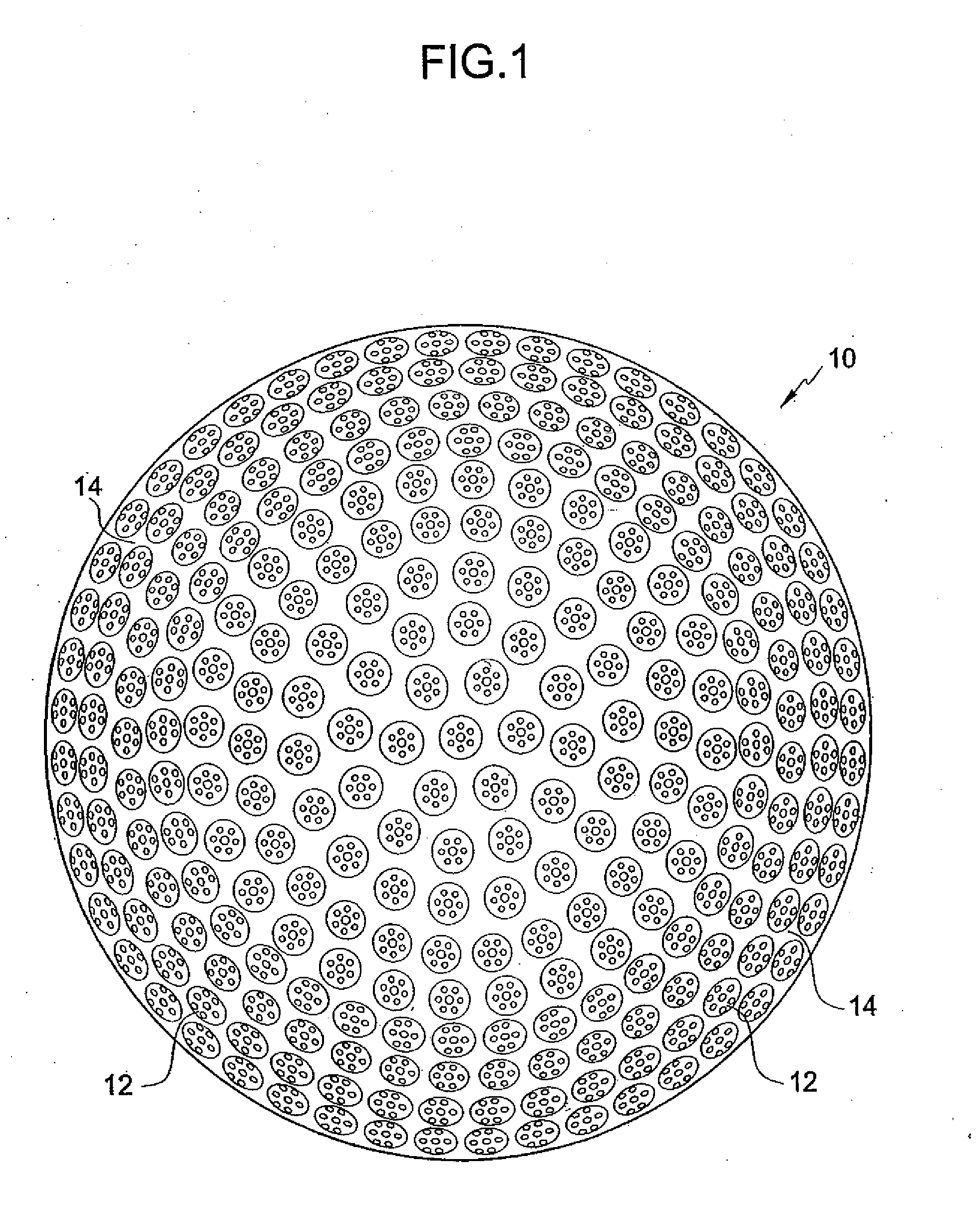
[0021] As shown generally in FIG. 1, where like numbers designate like parts, reference number 10 broadly designates a golf ball 10 having a plurality of dimples 12 separated by outer undimpled or land surface 14.

[0022] In accordance to one aspect of the present invention, dimples 12 may have sub-dimples defined on thereon to further agitate or energize the turbulent flow over the dimples and to reduce the tendency for separation of the turbulent boundary layer around the golf ball in flight. As described below, the sub-dimples may have many shapes and sizes, as long as they contribute to the agitation of the air flowing over the dimples.

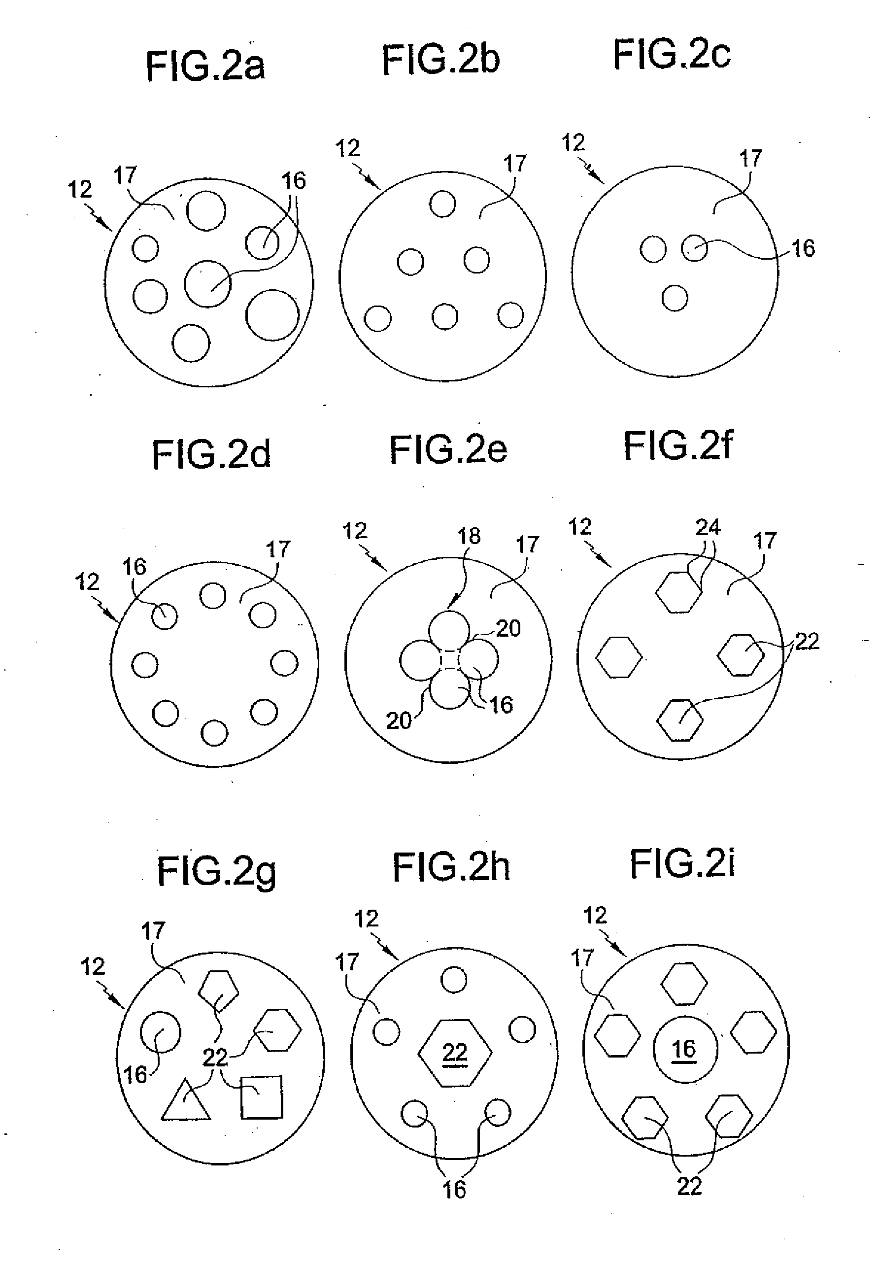
[0023]FIGS. 2a-2i illustrate sub-dimples 16 disposed on the land surface 17 of the dimple 12. As used herein, the land surface 17 of the dimple 12 is the concave surface of the dimple unaffected by the sub-dimples or other sub-structures defined on the dimple. For spherical dimples, the land surface 17 is spherical or arcuate. The land surface may...


PUM


Abstract

A golf ball has a substantially spherical outer surface comprised of a plurality of non-circular dimples. The dimples are formed by a plurality of lobes extending from a central hub, wherein each lobe is defined by a curved outer segment. The curved outer segments form at least a portion of the perimeter of the dimple. The dimples are comprised of at least four lobes. The dimples can also be comprised of a plurality of radiating arms emanating from a location proximate the hub of the dimple.

Description

CROSS REFERNCE TO RELATED APPLICATIONS [0001] This application is a divisional of co-pending U.S. application Ser. No. 10 / 789,288, filed Feb. 27, 2004, which is a continuation-in-part of U.S. application Ser. No. 10 / 338,379, filed Jan. 8, 2003, now U.S. Pat. No. 6,709,349, which is a continuation of U.S. application Ser. No. 09 / 847,764, filed May 2, 2001, now U.S. Pat. No. 6,569,038 which are incorporated by reference herein their entirety.FIELD OF THE INVENTION [0002] The present invention relates to golf balls, and more particularly, to a golf ball having improved dimples. BACKGROUND OF THE INVENTION [0003] Golf balls generally include a spherical outer surface with a plurality of dimples formed thereon. Conventional dimples are circular depressions that reduce drag and increase lift. These dimples are formed where a dimple wall slopes away from the outer surface of the ball forming the depression. [0004] Drag is the air resistance that opposes the golf ball's flight direction. As...

Claims


Application Information

Patent Timeline
Patent Type & Authority Applications(United States)
IPC IPC(8): A63B37/14A63B37/12A63B37/00
CPCA63B37/0004A63B37/0006A63B37/0015A63B37/0009A63B37/0007
Inventor SULLIVAN, MICHAEL J.
Owner ACUSHNET CO
Why Eureka
Try Eureka