
Easy marker placement balloon mold

a marker and mold technology, applied in the field of intravascular balloon catheters, can solve the problem that the manufacturing process does not readily lend itself to precise determination, and achieve the effect of quick and easy positioning and resistance to stent slippag

Inactive Publication Date: 2011-09-22
ABBOTT LAB INC
View PDF65 Cites 7 Cited by
  • Summary
  • Abstract
  • Description
  • Claims
  • Application Information

AI Technical Summary

Benefits of technology

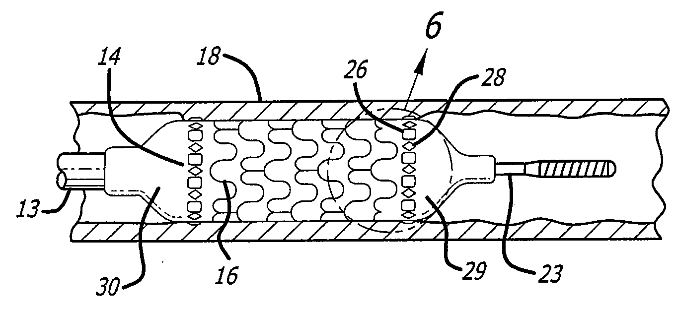
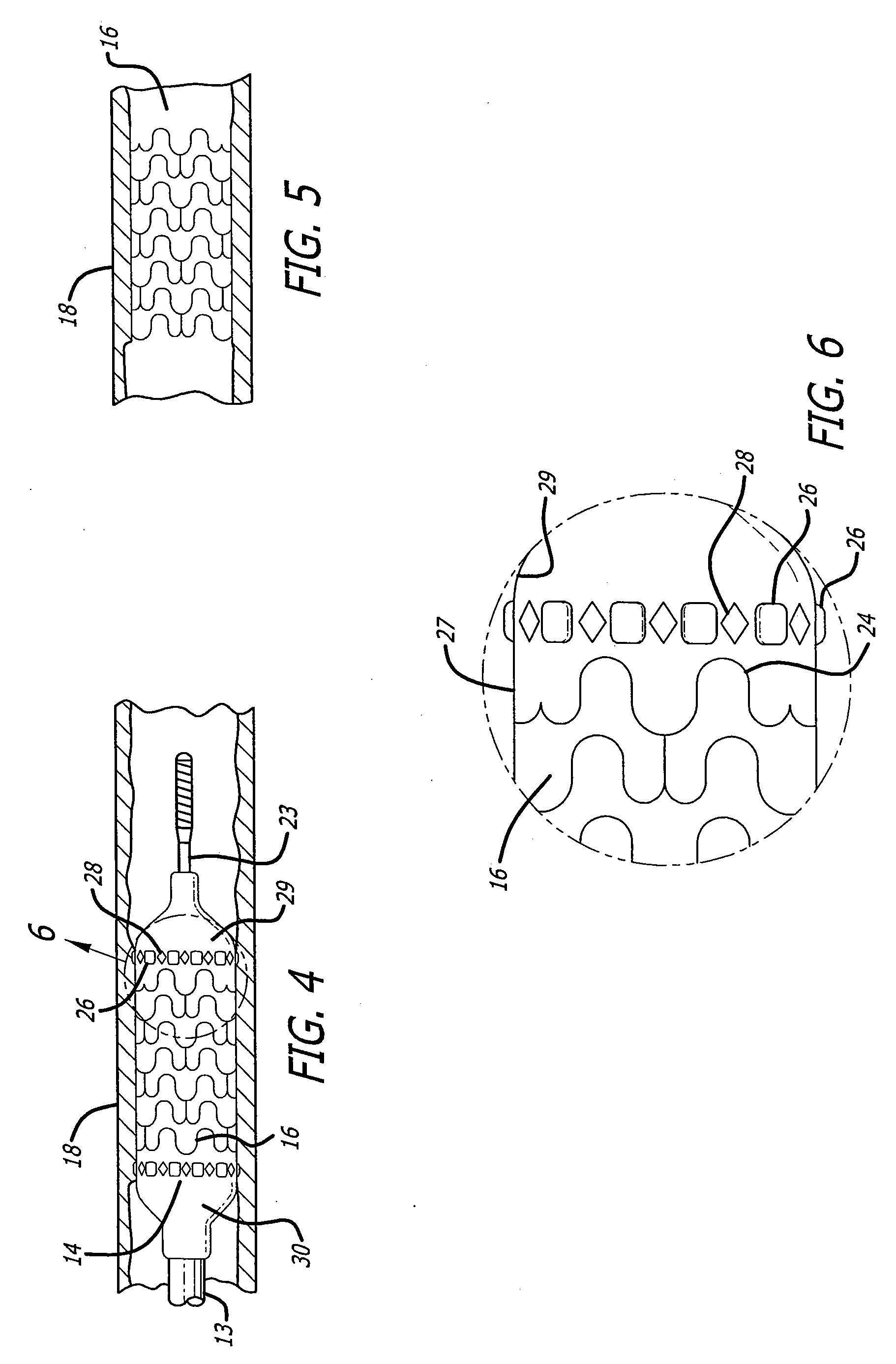
[0006]The present invention addresses the problem above by using a modified mold to create visual locators on the balloon that identify the proper position of the marker. A ring of visual locators on the balloon can be created by putting indentions or beads on the mold used to form the balloon, causing the balloon to have raised dimples in the case of indentations or shallow cavities in the case of beads on the working portion of the balloon right before the taper or neck portion. Henceforth the application shall refer to the visual markers as dimples but it is to be understood that cavities or divots would serve the same purpose and are considered part of the invention. The raised dimples enable the manufacturing operators who are tasked with placing the visual markers on the balloon to quickly and easily locate the visual markers precisely before the neck region but in the working area of the balloon every time. This also aids in the placement of stents that are mounted on the balloon in procedures that use this feature. The raised dimples also can assist in the retention of the stent on the balloon as it passes through the patient's vascular, where the raised dimples provide a resistance against slippage of the stent off of the balloon.

Problems solved by technology

Unfortunately, the manufacturing process does not readily lend itself to a precise determination as to where to apply the marker such that it is at the extreme end of the working portion of the balloon but does not extend to the neck portion.

Method used


Image

  • Easy marker placement balloon mold
  • Easy marker placement balloon mold
  • Easy marker placement balloon mold

Examples


Embodiment Construction

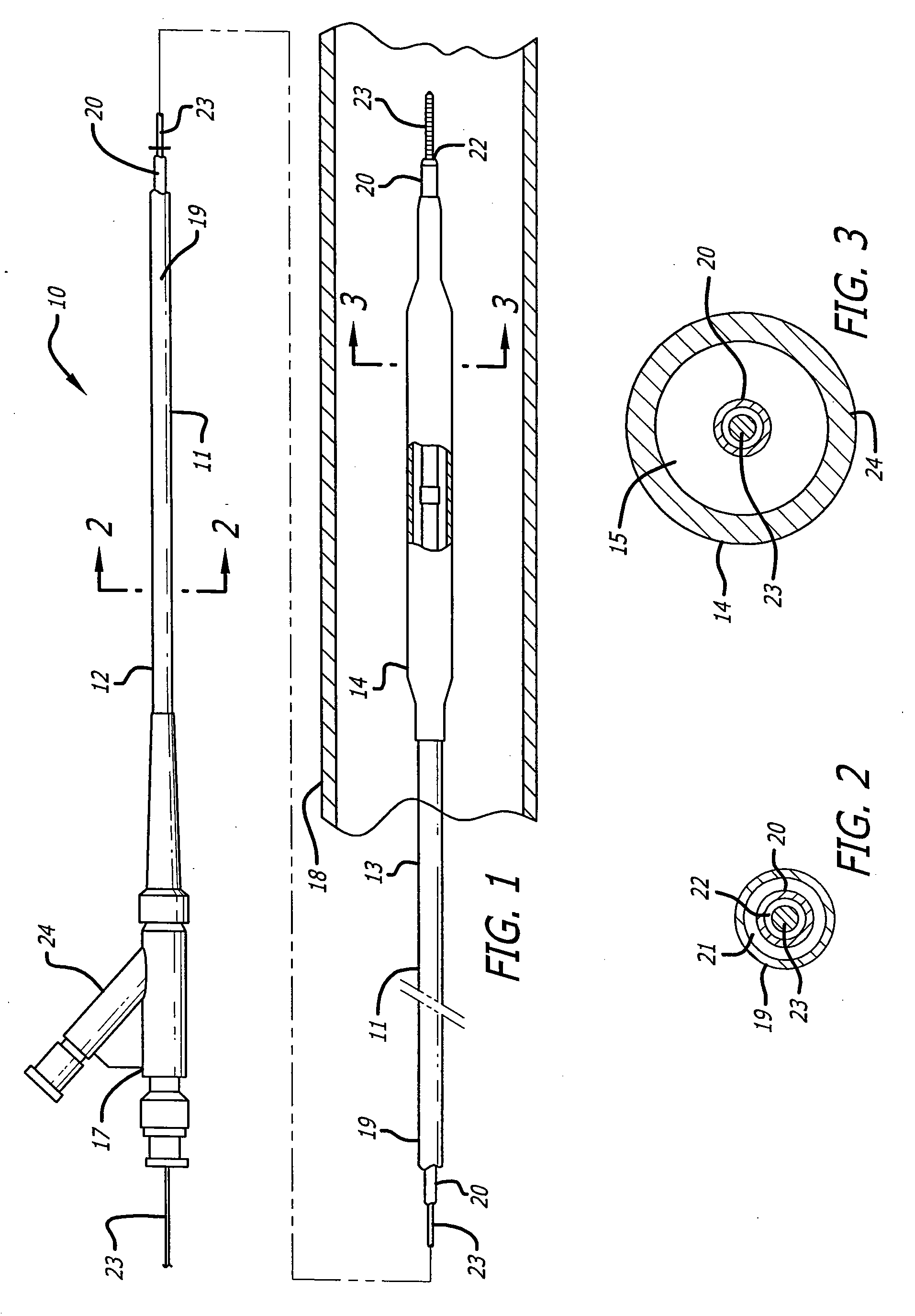
[0015]FIG. 1 shows a balloon catheter that can be used to illustrate the features of the invention. The catheter 10 of the invention generally comprises an elongated catheter shaft 11 having a proximal section 12, a distal section 13, an inflatable balloon 14 on the distal section 13 of the catheter shaft 11, and an adapter 17 mounted on the proximal section 12 of shaft 11. In FIG. 1, the catheter 10 is illustrated within a greatly enlarged view of a patient's body lumen 18, prior to expansion of the balloon 14, adjacent the tissue to be injected with therapeutic agents.

[0016]In the embodiment illustrated in FIG. 1, the catheter shaft 11 has an outer tubular member 19 and an inner tubular member 20 disposed within the outer tubular member and defining, with the outer tubular member, inflation lumen 21. Inflation lumen 21 is in fluid communication with the interior chamber 15 of the inflatable balloon 14. The inner tubular member 20 has an inner lumen 22 extending therein which is co...


PUM

PropertyMeasurementUnit
constant radiusaaaaaaaaaa
shapeaaaaaaaaaa
diameteraaaaaaaaaa

Abstract

A catheter balloon is formed from a mold process in which raised dimples or shallow divots are formed on the outer surface using indentations or raised beads on the mold surface. The dimples or divots are located at the transition between the body portion of the catheter balloon and the neck or taper section. The presence of the dimples or divots serves the dual purpose of identifying the transition between the two regions for placing a visual marker on the balloon to be used in positioning the balloon, and also to assist in the retention of a vascular stent on the balloon.

Description

BACKGROUND[0001]This invention generally relates to intravascular balloon catheters such as those used in percutaneous transluminal coronary angioplasty (PTCA) and stent delivery, and more particularly to a catheter balloon and mold for creating a balloon that permits reliable securement of positioning markers and stents.[0002]PTCA is a widely used procedure for the treatment of coronary heart disease. In this procedure, a balloon dilatation catheter is advanced into the patient's coronary artery and the balloon on the catheter is inflated within the stenotic region of the patient's artery to open up the arterial passageway and thereby increase the blood flow there through. To facilitate the advancement of the dilatation catheter into the patient's coronary artery, a guiding catheter having a preshaped distal tip is first percutaneously introduced into the cardiovascular system of a patient by the Seldinger technique or other method through the brachial or femoral arteries.[0003]The...

Claims


Application Information

Patent Timeline
Patent Type & Authority Applications(United States)
IPC IPC(8): A61F2/84A61M25/10B29C49/78B28B11/08
CPCA61F2/958A61F2002/9586A61M25/1029A61M25/104B29L2031/7542A61M2025/1086B29C49/48B29C2049/0089B29C2049/4882A61M2025/1079B29C2949/08
Inventor BUTCHER, DARA J.ARIPEZ, CARLOS A.
Owner ABBOTT LAB INC
Learn More