

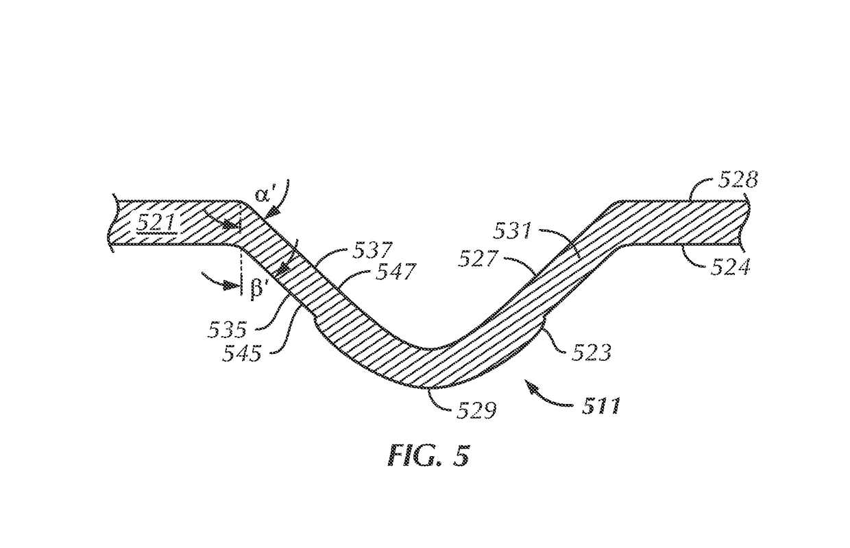
Punched gimbal dimple with a coined periphery in a head suspension
a technology of gimbal and periphery, which is applied in the direction of head support, record information storage, instruments, etc., can solve the problems of blind dimple dies, blind dimple dies are more difficult to fabricate than through hole dies, and dimples are difficult for optical systems to precisely locate, etc., to achieve easy optical system positioning, lower surface roughness average, and reduce the effect of roughness averag
- Summary
- Abstract
- Description
- Claims
- Application Information
AI Technical Summary
Benefits of technology
Problems solved by technology
Method used
Image

Examples
Embodiment Construction
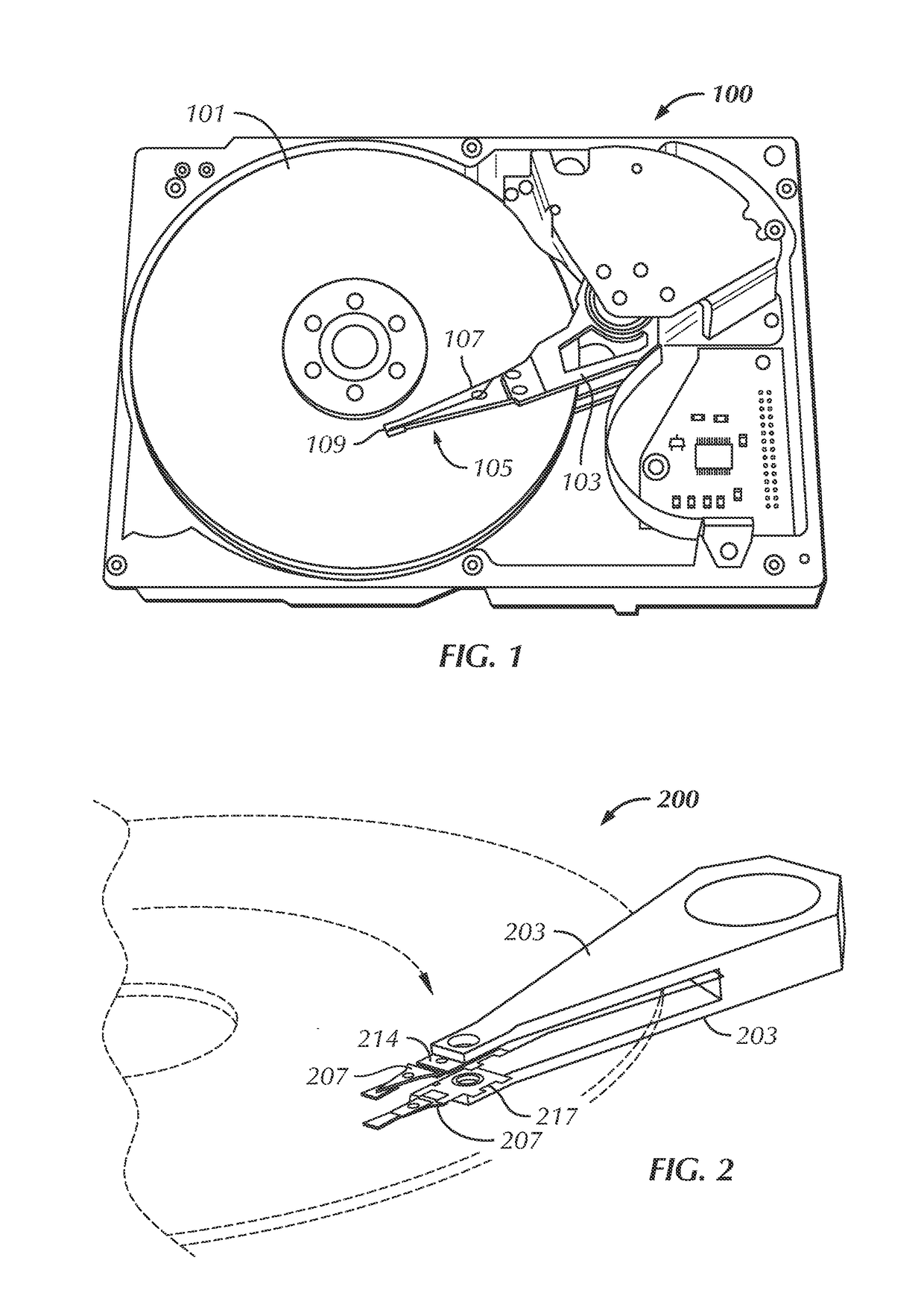
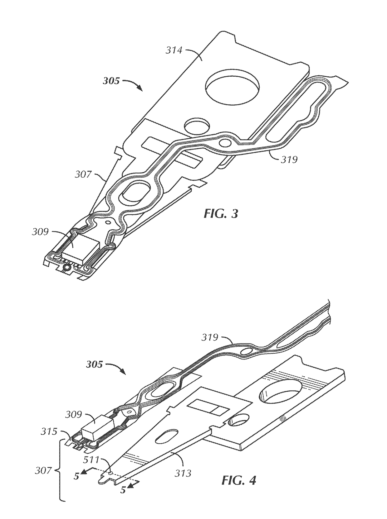
[0043]With reference to FIG. 1, a typical hard disk drive 100 includes at least one data storage disk 101 (e.g., one, two, three, or more disks), at least one actuator arm 103 (e.g., one, two, three, or more actuator arms), and at least one suspension assembly 105 (e.g., one, two, three, or more suspension assemblies). Each suspension assembly is composed of a head suspension 107 and a slider 109. This diagram, as well as other diagrams provided herein, is merely an example, which should not unduly limit the scope of the claims herein. One of ordinary skill in the art would recognize many other variations, modifications, and alternatives.
[0044]Disk 101, commonly called a platter, rotates about a fixed axis (or spindle) from about 5,000 rpm up to about 15,000 rpm depending upon the drive. Disk 101 stores information and thus often includes a magnetic medium such as a ferromagnetic material. However, it can also include optical materials, commonly coated on surfaces of the disk, which...
PUM
| Property | Measurement | Unit |
|---|---|---|
| peak-to-valley flatness | aaaaa | aaaaa |
| circumference | aaaaa | aaaaa |
| perimeter | aaaaa | aaaaa |
Abstract
Description
Claims
Application Information