
Eureka
For R&D, Eureka makes reading and utilizing patents & technical documents easy.
Eureka AIR
Designed for self-driven R&D workflows. Generate viable solutions, solve complex R&D challenges, empower your innovation with AI.

Eureka Materials
Designed for material experts only. Revolutionize your material R&D, from search, analyze, to developing new materials.

TechResearch
Generate reliable direction feasibility study reports for your R&D in just a few steps.

TechSeek
Discover and master advanced knowledge NOW. Basics, ideas, possibilities, all at once.

TechMind
As an expert in R&D Theories, TechMind can generates customized viable solutions instantly.

TechRisk
Analyze your overall solution with one click, know your potential R&D risks in advance.

TechMonitor
Get weekly tech updates, stay abreast of the latest tech innovations and key insights.
Coupling and angular position measuring device using the coupling
- Summary
- Abstract
- Description
- Claims
- Application Information
AI Technical Summary
Benefits of technology
Problems solved by technology
Method used
Image

Examples
Embodiment Construction
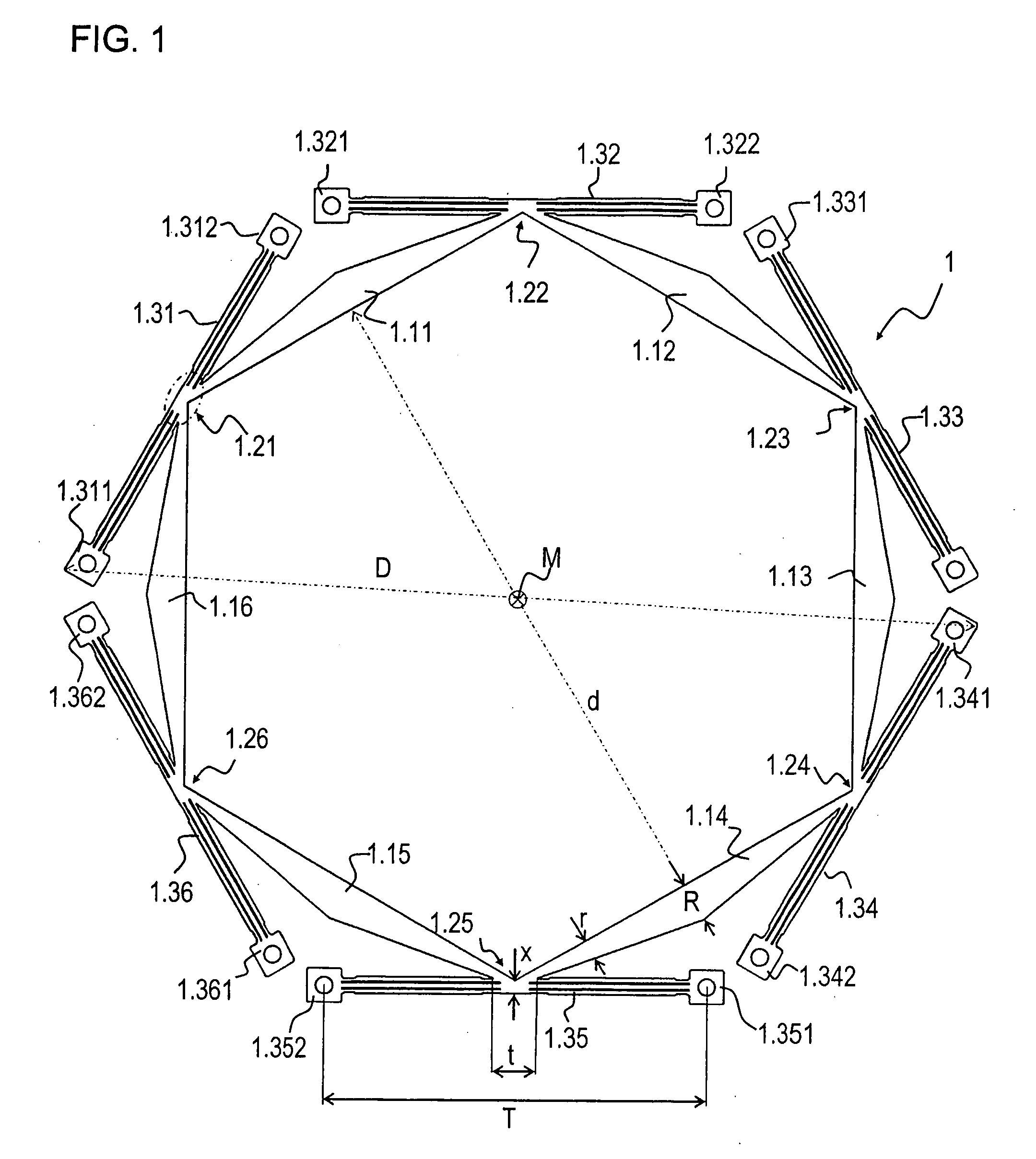
[0038]FIG. 1 is a top view of coupling 1 according to an example embodiment of the present invention. Coupling 1 is formed in one piece of sheet metal, the outer contours having been cut out of 2 mm thick flat sheet metal by a punching process. Coupling 1 includes six base elements 1.11 to 1.16 and six links or tabs 1.31 to 1.36. Between base elements 1.11 to 1.16 , six node areas 1.21 to 1.26 are also arranged. At node areas 1.21 to 1.26 , tabs 1.31 to 1.36 are correspondingly integrally formed over a length t. Thus, the connecting area of the tabs 1.31 to 1.36 to the node areas 1.21 to 1.26 has the length t. Although length t is illustrated only once in FIG. 1, this geometric view applies to all node area 1.21 to 1.26 and tabs 1.31 to 1.36. For clarity, dimensioning of other corresponding lengths is not provided. In FIG. 1, for example, node area 1.21 is indicated by an elliptical dash-dot line.
[0039] Coupling 1 may be arranged centrosymmetrically with respect to a center M. As i...
PUM
 Abstract
Description
Claims
Application Information
 - R&D Engineer
- R&D Manager
- IP Professional
- Industry Leading Data Capabilities
- Powerful AI technology
- Patent DNA Extraction
Browse by: Latest US Patents, China's latest patents, Technical Efficacy Thesaurus, Application Domain, Technology Topic, Popular Technical Reports.
© 2024 PatSnap. All rights reserved.Legal|Privacy policy|Modern Slavery Act Transparency Statement|Sitemap|About US| Contact US: help@patsnap.com