Oven

a technology for ovens and ovens, applied in the field of ovens, can solve problems such as increased user's unpleasantness and user's feelings of discomfor

Inactive Publication Date: 2006-12-14
SAMSUNG ELECTRONICS CO LTD
View PDF6 Cites 34 Cited by
  • Summary
  • Abstract
  • Description
  • Claims
  • Application Information

AI Technical Summary

Benefits of technology

[0010] In accordance with one aspect, the present invention provides an oven including: a cooking chamber disposed in a housing; a door to open and close the cooking chamber, the door having at least two air channels, which are separated from each other; a circulating fan in the housing outside the cooking chamber; and a channel connecting unit to connect suction and discharge parts of the circulating fan and the at least two air channels, wherein at least one of the air channels includes a first air channel, having one end connected to the discharge part of the circulating fan via the channel connecting unit and the other end connected to the outer space communicating with the lower end of the door, to guide air discharged by the circulating fan to the lower end of the door such that the air is discharged out of the oven through the lower end of the door. Consequently, the air blown by the circulating fan is discharged out of the oven through the lower end of the door via the channel connecting unit and the first air channel, and therefore, a user does not feel the unpleasantness of the discharged hot air.

Problems solved by technology

As a result, the hot air is directed to the face of a user, when the user observes the state of food being cooked, and therefore, the user feels unpleasantness.
Consequently, the user's unpleasantness is increased.

Method used


Image

  • Oven
  • Oven
  • Oven

Examples


Embodiment Construction

[0025] Reference will now be made in detail to embodiments of the present invention, examples of which are illustrated in the accompanying drawings, wherein like reference numerals refer to like elements throughout. The embodiments are described below to explain the present invention by referring to the figures.

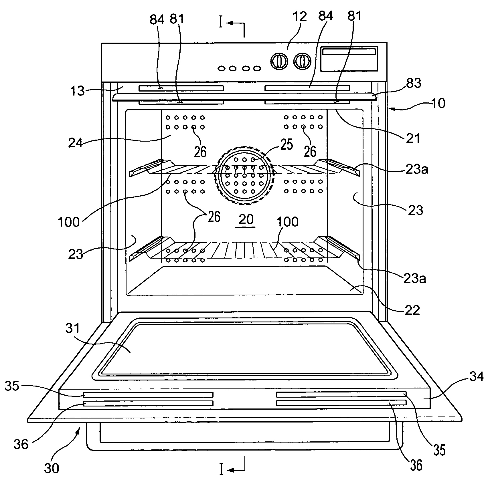
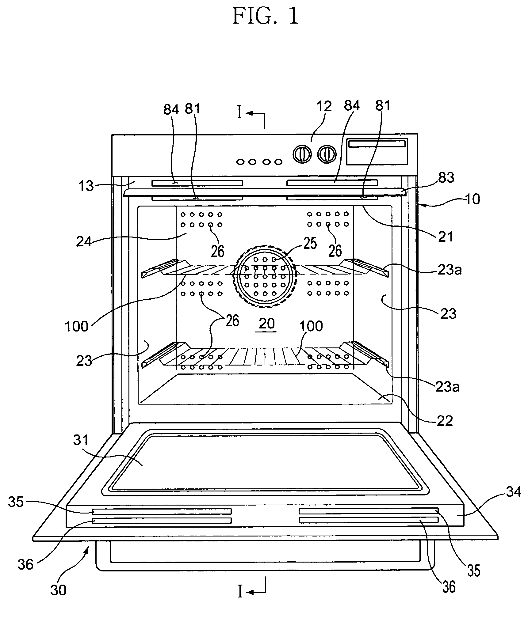
[0026]FIG. 1 is a front view showing an oven according to the present invention, FIG. 2 is a sectional view taken along line I-I of FIG. 1, and FIG. 3 is a plan view, in section, showing the structure of the oven according to the present invention.

[0027] As shown in FIGS. 1 and 2, the oven includes: a housing 10 having a cooking chamber 20 defined therein, the front surface of the cooking chamber 20 being opened; and a door 30 hingedly connected to the lower end of the housing 10 to open and close the opened front surface of the cooking chamber 20. The housing 10 and the door 30 form the outer appearance of the oven.

[0028] The cooking chamber 20 is a cooking space defined ...


PUM


Abstract

Disclosed herein is an oven that is capable of discharging hot air generated when cooling a door and heat generated in a cooking chamber through the lower end of the door. The oven includes a door having at least two separated air channels. The air channels comprise at least one first air channel to discharge hot air generated when cooling the door through the lower end of the door, and at least one second air channel to introduce air through the lower end of the door such that the door is cooled. In the housing is mounted a circulating fan. Between the circulating fan and the air channels is connected a channel connecting unit. As the circulating fan is rotated, air flows along the second air channel to cool the door. Hot air generated when cooling the door is introduced into the first air channel through the channel connecting unit, and is then discharged out of the oven through the lower end of the door.

Description

CROSS-REFERENCE TO RELATED APPLICATIONS [0001] This application claims the benefit of Korean Patent Application No. 2005-49756, filed on Jun. 10, 2005 in the Korean Intellectual Property Office, the disclosure of which is incorporated herein by reference. BACKGROUND OF THE INVENTION [0002] 1. Field of the Invention [0003] The present invention relates to an oven and, more particularly, to an oven that is capable of discharging hot air generated when cooling a door and heat generated in a cooking chamber through the lower end of the door. [0004] 2. Description of the Related Art [0005] Generally, an oven is a kitchen appliance that heats food, which is placed in an enclosed cooking space, to cook the food. Based on heat sources, ovens are classified into an electric oven, a gas oven, and a microwave oven. The electric oven uses an electric heater as the heat source, the gas oven uses gas heat as the heat source, and the microwave oven uses frictional heat of water molecules due to mi...

Claims


Application Information

Patent Timeline
Patent Type & Authority Applications(United States)
IPC IPC(8): F24C15/32
CPCF24C15/04F24C15/006F24C15/02F24C15/34E05Y2900/308
Inventor PARK, SUNG SOOCHO, PUNG YEUNKIM, CHEOL JINKIM, KYOUNG HOLEE, KIL YOUNGKIM, SUNG KWANGHA, YU JEUBHWANG, YUN ICKANG, SANG HYUNHONG, SEOK WEONKIM, TAE HO
Owner SAMSUNG ELECTRONICS CO LTD
Why Eureka
Try Eureka