Equipment fan

a technology of equipment fan and fan body, which is applied in the direction of motors, electrical equipment, electrical apparatus, etc., can solve the problems of difficult removal of fans, for instance for repair or replacement with a new fan, and achieve the effect of easy replacemen

Inactive Publication Date: 2006-12-14
EBM PAPST ST GEORGEN & -
View PDF7 Cites 73 Cited by
  • Summary
  • Abstract
  • Description
  • Claims
  • Application Information

AI Technical Summary

Benefits of technology

[0007] It is therefore an object of the present invention to p

Problems solved by technology

Because electronic components are used in many different kinds of equipment, equipment fans are necessary and must be installed even at poorly accessible points, such as in veh

Method used


Image

  • Equipment fan
  • Equipment fan
  • Equipment fan

Examples


Embodiment Construction

[0030] In the following description, the terms left, right, top and bottom pertain to the applicable drawing figure, and depending on the orientation chosen (vertical or horizontal) may vary from one drawing figure to the next. Elements that are the same or function the same are designated by the same reference numerals in the various drawings, and will usually be described only once.

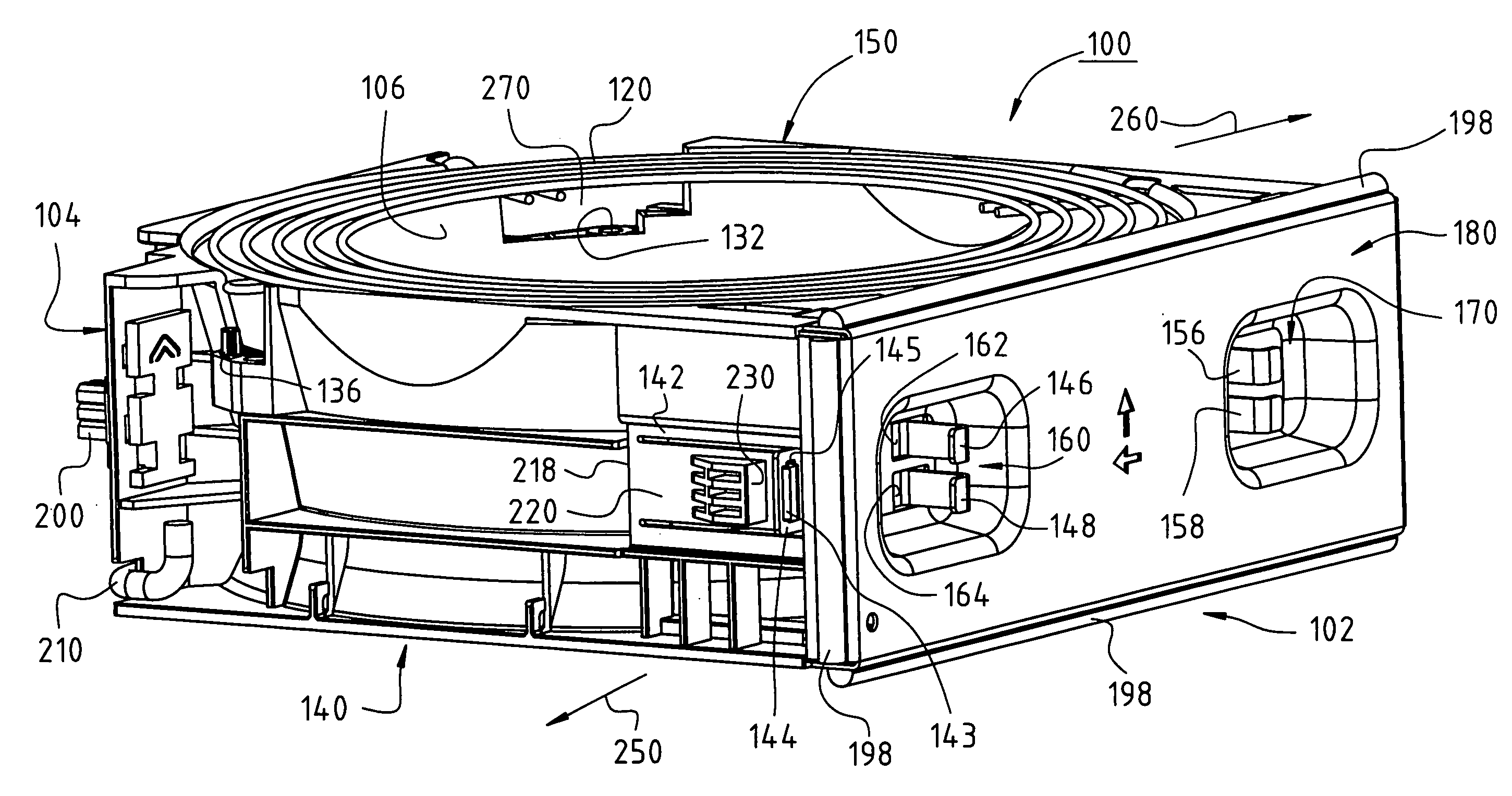
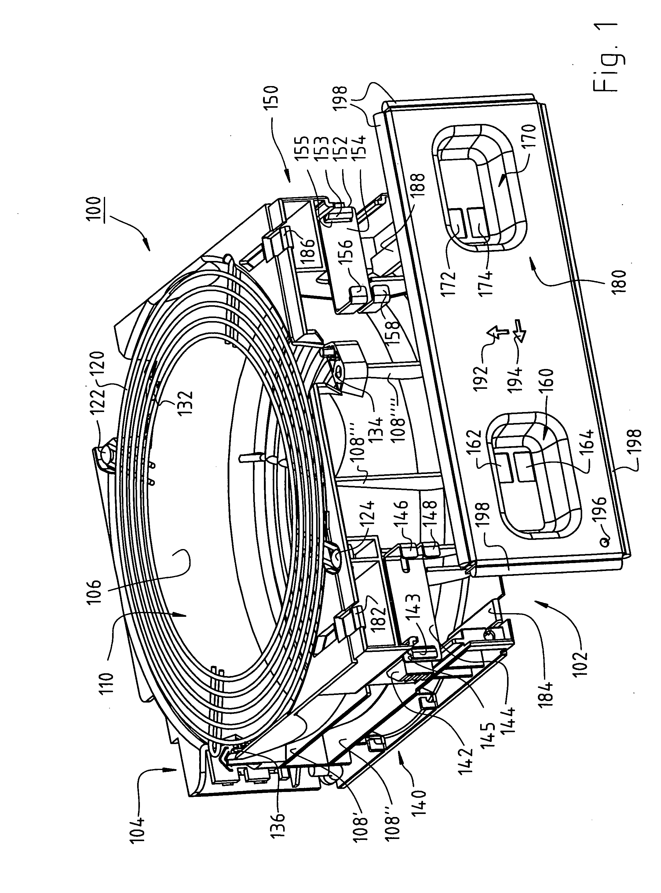
[0031]FIG. 1 is an enlarged top view on the top side of a fan housing 100 in a preferred embodiment of the invention. This housing has a recess 110 for a fan wheel assembly 20 (FIG. 6), which is bounded by a frustoconical tube 106, for instance. This tube, because of its function, is also known as a Venturi tube 106. On its outsides, the housing 100 has various structural elements, such as reinforcements or braces 108′, 108″, 108′″ and 108″″, of the kind that are used in building housings, and they will therefore not be described here in detail.

[0032] The shape of the outline of the housing 100 is app...


PUM


Abstract

An equipment fan has a housing (100) which is configured as a plug-in module for an equipment rack. The housing has a front side (102) and a back side (104), the latter being slid into the equipment rack (320) first upon installation. For latching into this kind of equipment, the housing (100) has at least one resiliently deflectable detent member (142, 152), which, for its actuation, is associated with a respective actuation member (144, 154) that is operable from the front side of the housing. Troughs (160, 170) are located on the front side (102), and a respective actuator (146, 148, 156, 158) for each deflectable member is located in each. The detent member (142, 152) has pretensioning which urges the detent member away from the housing (100) so that, when the housing is slid into a piece of equipment, latching of the housing (100) therein is accomplished.

Description

CROSS-REFERENCE [0001] This application claims priority from my German application DE 20 2005 009 522.2 of 10 Jun. 2005, the entire content of which is hereby incorporated by reference. FIELD OF THE INVENTION [0002] The invention relates to an equipment fan, having a housing which is configured for installing the equipment fan in a piece of equipment. BACKGROUND [0003] Electronic components in equipment such as computers usually require cooling. To provide such cooling, equipment fans are used, which are located in a housing. [0004] Because electronic components are used in many different kinds of equipment, equipment fans are necessary and must be installed even at poorly accessible points, such as in vehicles of all kinds where space is often very scarce. In such concealed places, removing a fan, for instance for repair or for replacement with a new fan, is often very difficult. [0005] In certain applications, it must be possible to swap out an equipment fan very quickly, so that ...

Claims


Application Information

Patent Timeline
IPC IPC(8): H05K7/20
CPCF04D29/023H05K7/20172F04D29/601F05D2230/51F05D2300/507
Inventor STROHM, RAINER
Owner EBM PAPST ST GEORGEN & -
Why Eureka
Try Eureka