Fuel cell system

a fuel cell and system technology, applied in battery/fuel cell control arrangement, electrochemical generators, transportation and packaging, etc., can solve the problems of increasing the manufacturing cost of the fuel cell system, the fuel cell often stops or does not generate electrical power, and the fuel cell system becomes a complicated configuration, so as to reduce the generation efficiency of electrical power, increase the heat energy generated in the fuel cell, and increase the efficiency of the fuel cell

Inactive Publication Date: 2006-12-14
DENSO CORP
View PDF11 Cites 88 Cited by
  • Summary
  • Abstract
  • Description
  • Claims
  • Application Information

AI Technical Summary

Benefits of technology

[0015] Because the auxiliary equipment can operate by supplying the electrical power from the fuel cell, it is not necessary for the secondary battery to supply the electric power to the auxiliary equipment and it is possible to keep the warm-up function of the fuel cell, namely the cold starting capability of the fuel cell in a cold temperature environment. In addition, because the fuel cell can operate at the operating poi

Problems solved by technology

When a fuel cell commences the electrical power generation in a low temperature environment by the electrochemical reaction of hydrogen and oxygen, the fuel cell often stops or does not generate the electrical power because residual water that has been generated in previous electrochemical reaction in the fuel cell is frozen.
However, this conventional technique requires an additional electric component such as a variable resistance and thereby the fuel cell system becomes a complicated configuration because of mounting the additional variable resistance.
The manufacturing cost of the fuel cell system is thereby increased.
It be

Method used


Image

  • Fuel cell system
  • Fuel cell system
  • Fuel cell system

Examples


first embodiment

[0031] A description will now be given of the fuel cell system according to the first embodiment of the present invention with reference to FIG. 1 to FIG. 5. Following plural embodiments of the present invention will show the fuel cell system of the present invention that is applied to an electric vehicle or a fuel cell vehicle equipped with a fuel cell stack (FC stack) as an electric power source.

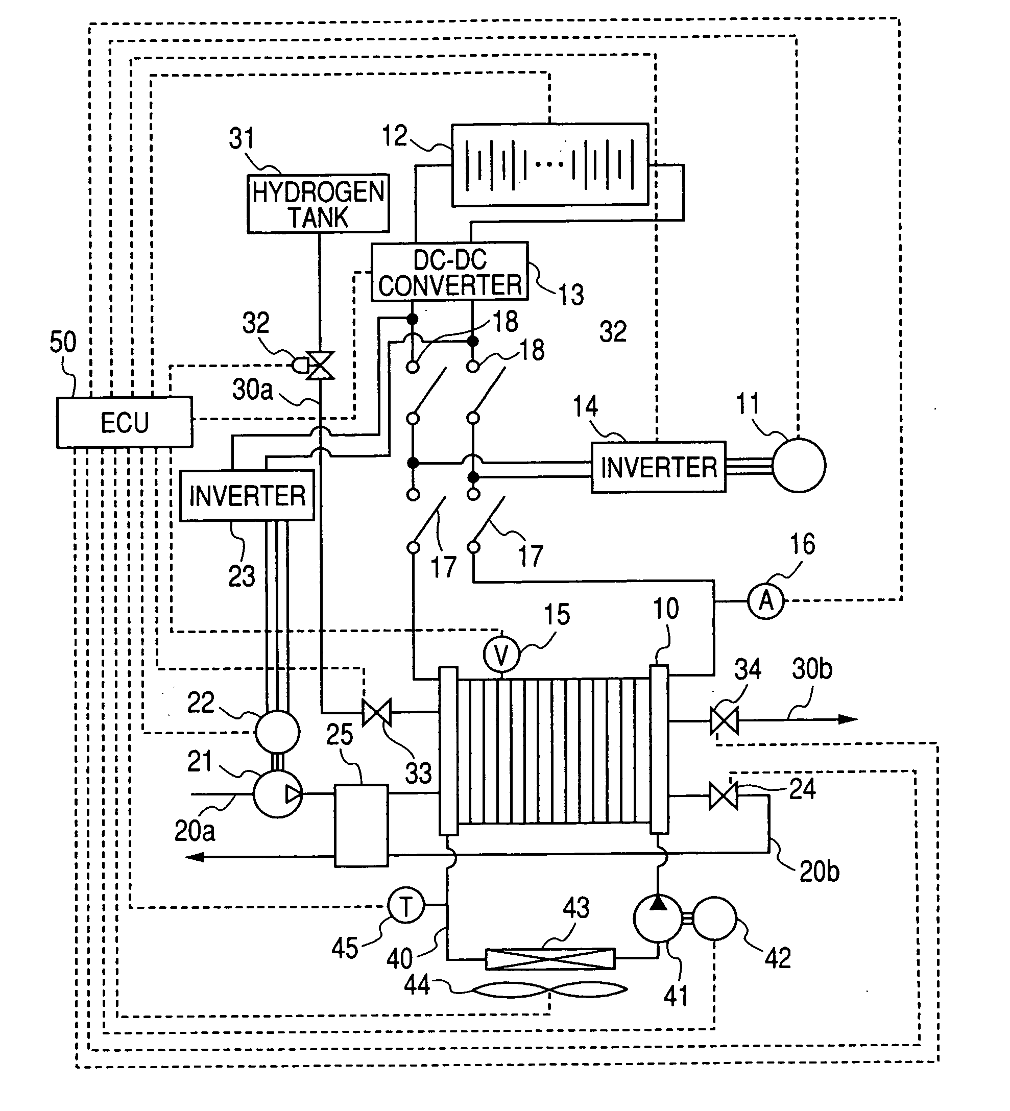
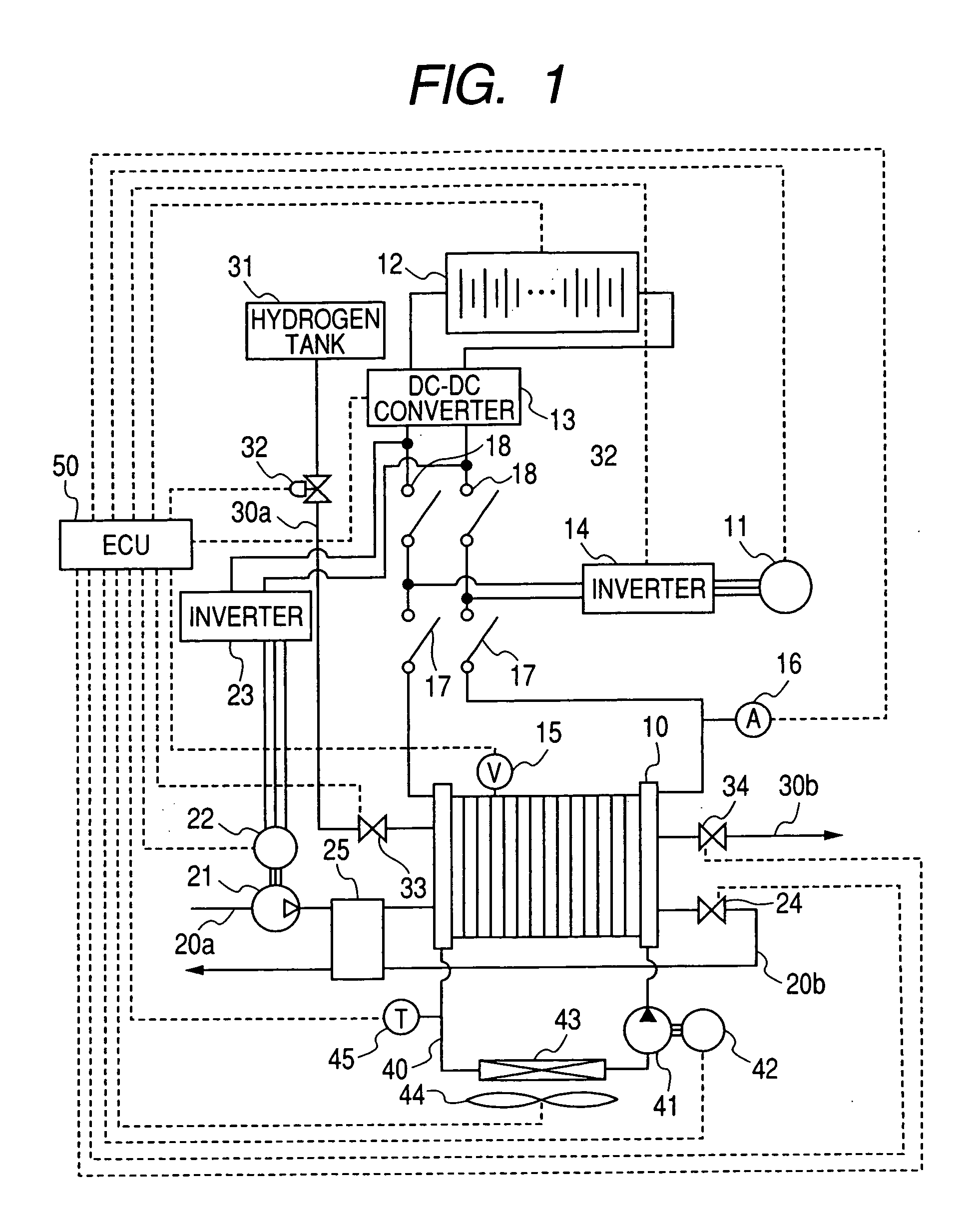
[0032]FIG. 1 is a schematic diagram showing the entire configuration of the fuel cell system according to first to fourth embodiments of the present invention. As shown in FIG. 1, the fuel cell system of the present invention is equipped with the fuel cell stack (FC stack) 10 that generates electrical power by electrochemical reaction of combining hydrogen and oxygen. The fuel cell 10 supplies the generated electrical power to electrical components mounted on a vehicle, such as a drive motor 11, a secondary battery 12, and auxiliary equipment (electric motor) 22. The auxiliary equipment 2...

second embodiment

[0107] Next, a description will now be given of the fuel cell system according to the second embodiment with reference to FIG. 6.

[0108] If residual water remains in the fuel cell 10 at the completion of the electrical power generation, there is a possibility that the residual water in the fuel cell 10 will be frozen in a low temperature environment. On re-starting the fuel cell 10 mounted on a vehicle in a low temperature environment, there is a great possibility to be difficult to perform electrochemical reaction in the fuel cell 10 and also difficult to start-up the operation of the fuel cell 10 even if reaction gases (Hydrogen and Air) are supplied to the fuel cell 10 because frozen water plug reaction-gas supply paths and prevents the supply of the reaction gases to polymer electrolyte films in the fuel cell 10.

[0109] The fuel cell system according to the second embodiment has an improved cold starting capability in which the warm-up operation is performed at the stoppage of t...

third embodiment

[0128] Next, a description will now be given of the fuel cell system according to the third embodiment.

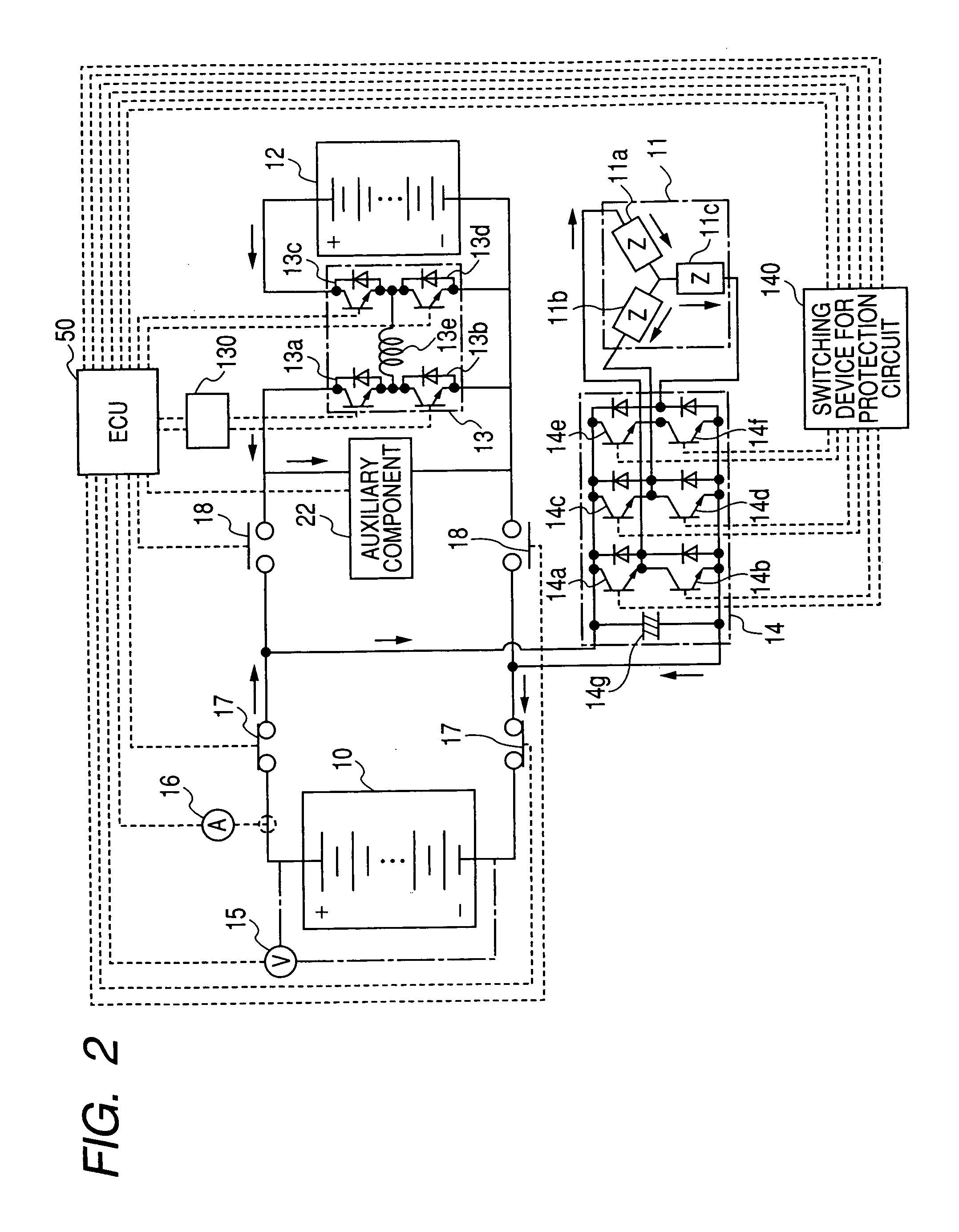
[0129] In the first and second embodiments described above, the fuel cell system is so controlled that both the switching elements 13a and 13d are turned ON simultaneously when the electrical power generated in the fuel cell 10 is supplied to the secondary battery 12.

[0130] The fuel cell system of the third embodiment has the same function of the fuel cell systems of the first and second embodiments, which changes the amount of current output from the fuel cell 10 by adjusting the switching frequency while performing the ON / OFF control for the switching elements 13a and 13d.

[0131] Because it is possible to flow the large amount of current from the fuel cell 10 during usual operation, the control section 50 controls the switching elements 13a and 13d by using a high frequency (for example, not less than 10 kHz). Using a low switching frequency makes a long-period ON state of both...


PUM


Abstract

A fuel cell system equipped with a fuel cell that generates electrical power in electrochemical reaction of hydrogen and oxygen. The system has the improved cold starting capability that increases heat energy generated in the fuel cell in order to rise the temperature of the fuel cell rapidly in a cold temperature environment. The system has an inverter having plural switching elements connected in series and a control section for controlling ON/OFF operation of the plural switching elements. The control section controls the amount of current output from the fuel cell by performing the ON/OFF control of the switching elements. On commencing the cold starting process of the fuel cell, the control means changes the current path in a drive motor by performing the ON/OFF control of the switching elements, in which both the inverter and the drive motor are used as a variable resistance to the fuel cell.

Description

CROSS-REFERENCE TO RELATED APPLICATIONS [0001] This application is related to and claims priority from Japanese Patent Applications No. 2005-169238 filed on Jun. 9, 2005 and No. 2005-174989 filed on Jun. 15, 2005, the contents of which are hereby incorporated by reference. BACKGROUND OF THE INVENTION [0002] 1. Field of the Invention [0003] The present invention relates to a fuel cell system with a fuel cell (FC stack) that generates electrical energy in electrochemical reaction of combining hydrogen and oxygen, and suitably applicable to movable bodies, equipped with a fuel cell system such as an electrical power source, such as in automotive vehicles, electric vehicles, marine vessels, portable power generators, small-sized generators, and other mobile devices. [0004] 2. Description of the Related Art [0005] When a fuel cell commences the electrical power generation in a low temperature environment by the electrochemical reaction of hydrogen and oxygen, the fuel cell often stops or...

Claims


Application Information

Patent Timeline
IPC IPC(8): H01M8/04
CPCB60L11/1885Y02E60/50B60L11/1894H01M8/04007H01M8/04268H01M8/04358H01M8/04559H01M8/04589H01M8/04723H01M8/04753H01M8/04761H01M8/04768H01M8/04947H01M2008/1095H01M2250/20Y02T90/32Y02T90/34B60L11/1892B60L58/31B60L58/33B60L58/34Y02T90/40
Inventor SAKAJO, YUICHIKAWAI, TOSHIYUKIIZUHARA, HIDESHIFUJITSUNA, MASAMI
Owner DENSO CORP
Why Eureka
Try Eureka