Recirculating Shower System

a shower system and circulating technology, applied in the field of circulating shower systems, can solve the problems of limiting the power available to heat up the water as it passes through the shower heater, requiring more complicated plumbing than electric showers, and unusable electric showers, etc., and achieve the effect of reducing energy requirements

Inactive Publication Date: 2014-02-06
CHRISTY NICHOLAS
View PDF2 Cites 8 Cited by
  • Summary
  • Abstract
  • Description
  • Claims
  • Application Information

AI Technical Summary

Benefits of technology

[0021]Referring to the forms of the invention above, the energy recirculating system of the invention reduces energy requirements by efficiently transferring the existing energy within the system, resulting in a system which requires minimal, if any, additional heat energy to be input to the system.

Problems solved by technology

One problem with the use of recirculating showers in domestic applications lies in regulations that require that any water mixed with mains water must meet water purity standards that the waste water from a shower does not meet.
The maximum power that can be drawn from a standard domestic electricity supply of 240 volts (for example in Australia and across Europe) is 7.5-11.5 kW, which limits the power that is available to heat up the water as it passes through the shower heater.
In some parts of the world, this problem is made worse since the maximum power that can be drawn is lower than 7 kW, e.g. in some areas of China, the maximum power that can be drawn is 3 kW, which ultimately can make electric showers unusable due to the extremely low flow rate of heated water.
They therefore require more complicated plumbing than electric showers.
In addition, if the water supply is not constant, e.g. because someone else is drawing hot water, the temperature of the shower can fluctuate.
However, whilst the system is up to 70% more energy and water efficient than a conventional shower, it has a number of weaknesses, including:The heater requires up to 9 kW of power to provide a shower with a flow rate of 10 litres per minute.
This is expensive and disruptive to install.
In developing nations this can be more power than is supplied to a house via domestic supply, making the shower system not viable in those countries.The water recirculation percentage achieved by the system is dependent on the ambient water temperature of the cold water supplied; the warmer the cold water input, the less water can be recycled.

Method used


Image

  • Recirculating Shower System
  • Recirculating Shower System

Examples


Embodiment Construction

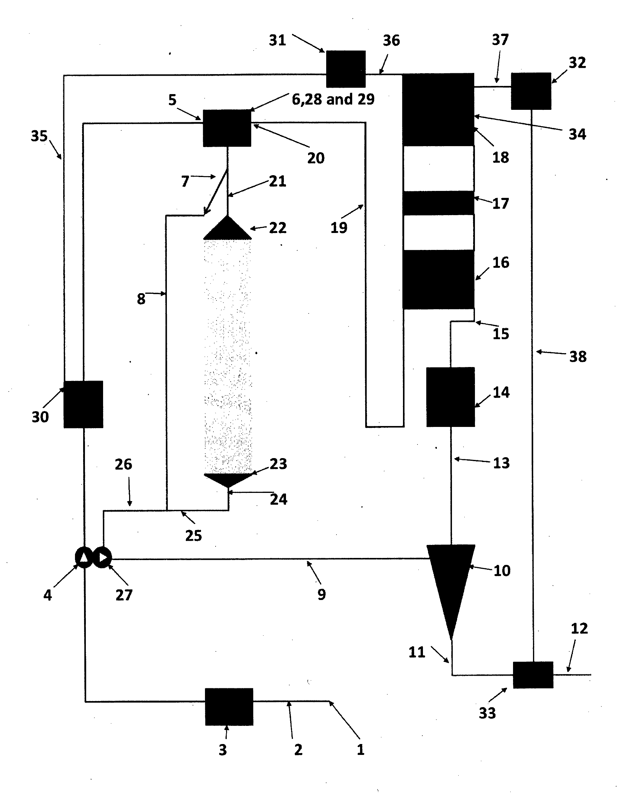
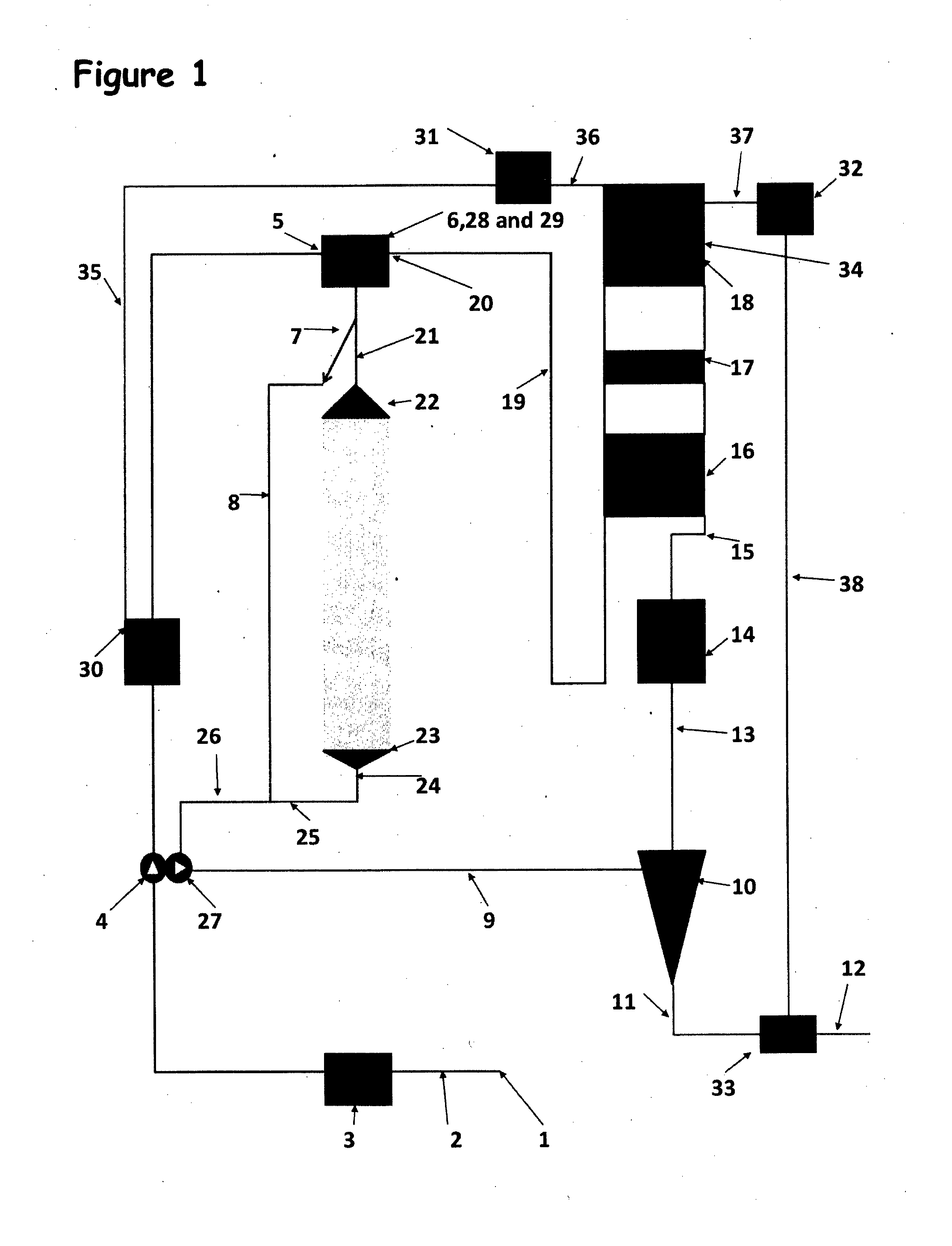
[0029]A detailed, non-limiting example of the use of the invention in a recirculating shower system, such as that described in WO2006 / 131743 is provided.

[0030]Referring to FIG. 1, in a shower system of the invention, the mains water (1) is introduced to the system via a water pipe (2) passing through a hydraulic jump (3), which prevents water passing back from the system into the mains water, and is pumped by a pump (4) through the cold water inlet (5) of a shower mixer (6). The mixer adjusts the relative cold and hot flows until the mixed flow is at the required temperature for the shower. This will be discussed in more detail below.

[0031]The mixed water passes from the mixer to a bypass valve (7) which can direct the shower water to either:[0032]The showerhead (22) via a pipe or hose (21), or[0033]To a bypass circuit (8).

[0034]When the shower is turned on the bypass valve is set automatically to direct the water to the bypass circuit (8), diverting water away from the showerhead (...


PUM


Abstract

The invention provides a recirculating shower system comprising a showerhead and shower tray, a circuit configured to collect used water from the shower tray and to recirculate at least part of the used water to the showerhead for further use, the circuit including at least one heat pump to exchange heat between relatively hot water and relatively cold water.

Description

FIELD OF INVENTION[0001]This invention relates to a recirculating shower system. In particular the invention relates to a recirculating shower system in which energy is transferred in the recirculation circuit by one or more heat pumps.BACKGROUND[0002]Water recirculating systems are known for many applications. For example, showers that are arranged to recirculate water within the shower and thereby use less water. Recirculating showers find application principally in portable and mobile applications such as boats and camping vans. For example U.S. Pat. No. 4,828,709 describes a recirculating shower system for use on boats and recreational vehicles. The recirculating water system, which operates with water from a non-mains water supply in the boat or vehicle, comprises filters, a water heater and fresh and used water storage tanks.[0003]In many parts of the world, fresh water is in short supply and measures are taken to preserve the water supply, and there are often incentives offer...

Claims


Application Information

Patent Timeline
Patent Type & Authority Applications(United States)
IPC IPC(8): A47K3/28
CPCA47K3/28E03C1/00E03C2001/005Y02B30/52
Inventor CHRISTY, NICHOLAS
Owner CHRISTY NICHOLAS
Why Eureka
Try Eureka