Communication system for electrical maintenance management of different facilities and method therefor

a technology for electrical maintenance and communication system, applied in the field of maintenance system, can solve the problems of large amount of time, energy and cost, degradation of store brand identity and top-of-mind awareness, and constant turnover of approved vendors, and achieve the effect of improving communication and operational standards

Inactive Publication Date: 2006-12-14
BERG DAVID A
View PDF4 Cites 9 Cited by
  • Summary
  • Abstract
  • Description
  • Claims
  • Application Information

AI Technical Summary

Benefits of technology

[0012] In accordance with one embodiment of the present invention, it is an object of the present invention to provide an improved communication system and method for maintenance of electrical, mechanical, plumbing, and other systems of a facility.
[0014] It is still another object of the present invention to provide an improved communication system and method that will send out work orders to designated maintenance companies for maintenance on systems of a designated facility.

Problems solved by technology

When store lighting, POPs and signs are not working correctly, degradation of the stores brand identity and top-of-mind awareness suffers.
A large amount of time, energy and costs are spent managing vendor issues such as product and labor cost controls, on-site work rules and regulations, schedules, follow-up effort, billing procedures, insurance updates, etc.
Another problem that compounds management costs is the constant turnover of approved vendors due to lack of performance and follow-through.
This is largely due to the absence of a standard communications platform that both the Clients and Vendors can work within.
By reducing internal staff and relying on out-sourced maintenance management, a large reduction of internal overhead is being experienced, but an additional layer of mark-up costs is occurring.
The improved communication system and method must over come the problems associated with prior art systems and methods.

Method used


Image

  • Communication system for electrical maintenance management of different facilities and method therefor
  • Communication system for electrical maintenance management of different facilities and method therefor
  • Communication system for electrical maintenance management of different facilities and method therefor

Examples


Embodiment Construction

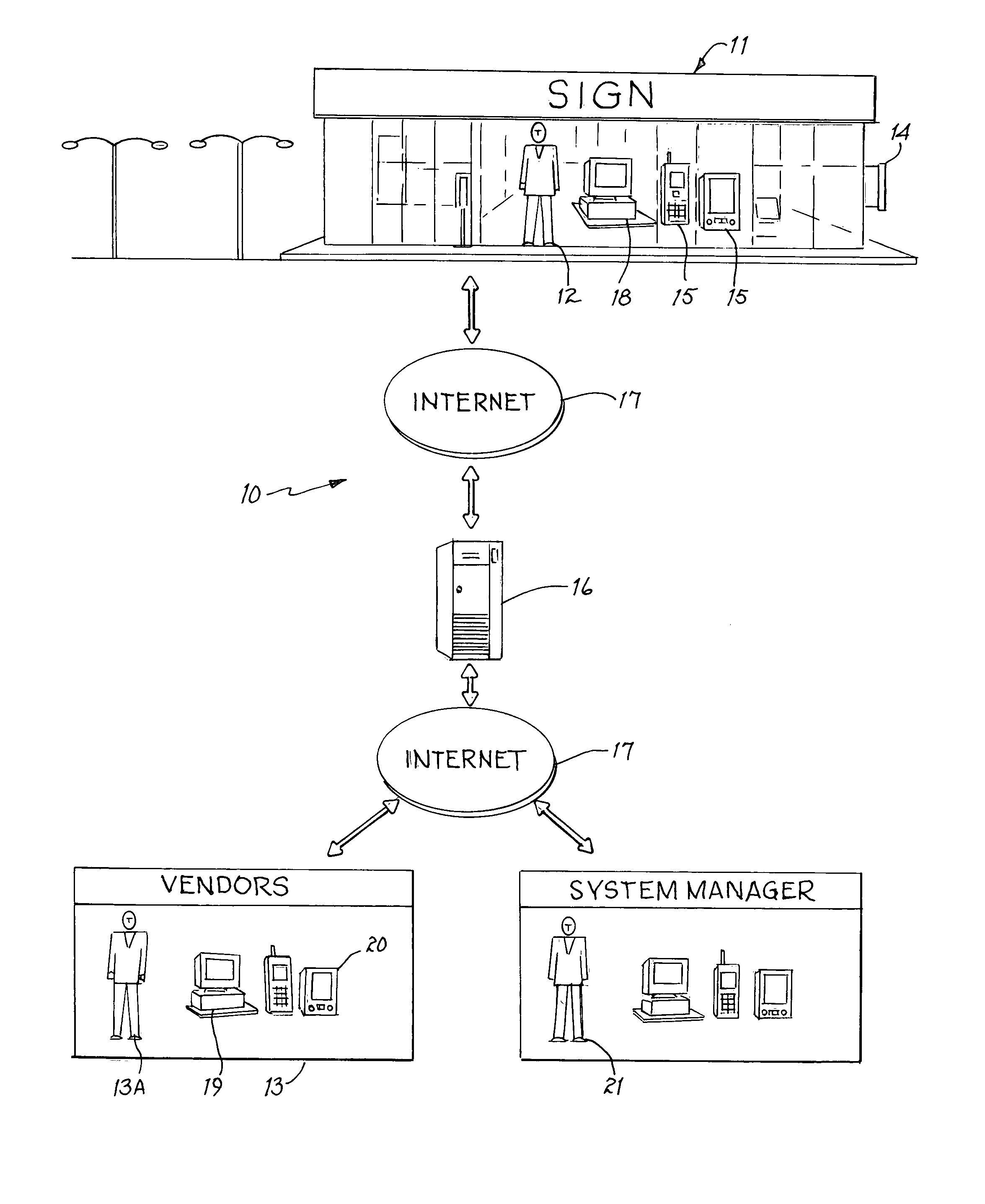
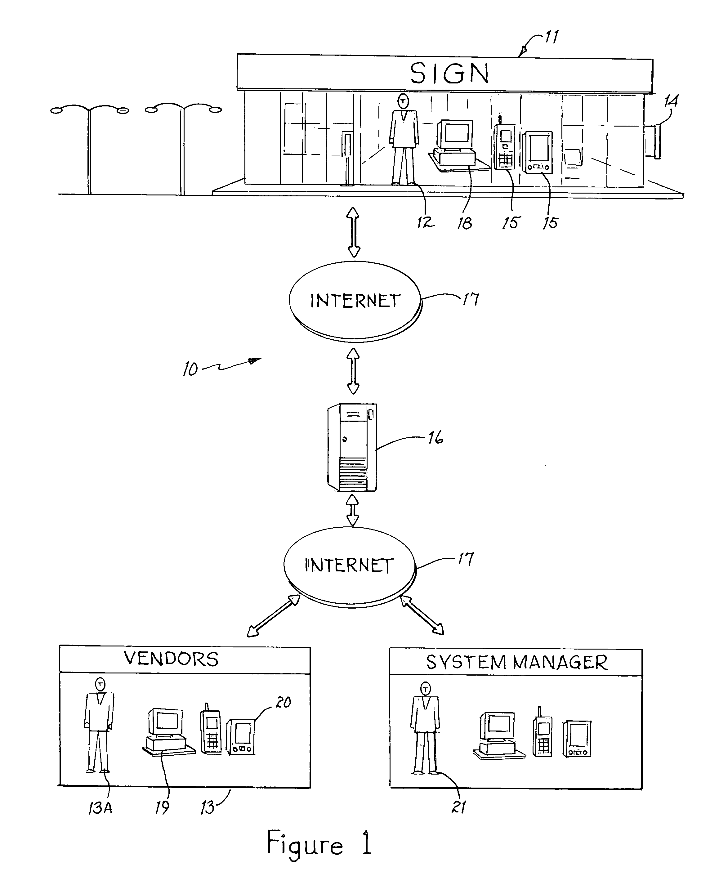
[0016] In accordance with one embodiment of the present invention, a communication system for monitoring operation of a system in a facility and for sending out repair request is disclosed. The communication system has a monitoring device coupled to a system in the facility to be monitored. The monitoring device sends a notification signal when an operational problem is monitored. A receiving device is used for receiving the notification signal sent from the monitoring device. A client computer system is utilized for entering information for a repair order for the operational problem monitored. A repair maintenance server is coupled to the first computer system. The repair maintenance server receives the repair order information and sends bid requests to designated repair vendors. A plurality of vendor communication systems is coupled to the repair maintenance server for repair vendors to submit bids for the repair order. The repair maintenance server will select a vendor and notify...


PUM


Abstract

A communication system and method for monitoring operation of a system in a facility and for sending out repair request has a monitoring device coupled to a system in the facility to be monitored. The monitoring device sends a notification signal when an operational problem is monitored. A receiving device is used for receiving the notification signal sent from the monitoring device. A client communication system is utilized for entering information for a repair order for the operational problem monitored. A repair maintenance server is coupled to the first computer system. The repair maintenance server receives the repair order information and sends bid requests to designated repair vendors. A plurality of vendor computer systems is coupled to the repair maintenance server for repair vendors to submit bids for the repair order. The repair maintenance server will select a vendor and notify the vendor of a winning bid.

Description

BACKGROUND OF THE INVENTION [0001] 1. Field of the Invention [0002] This invention relates generally to maintenance systems, and more specifically, to a communication system and method which will send out work orders to designated maintenance companies for maintenance on electrical, mechanical, plumbing, or other systems of a designated facility. [0003] 2. Description of the Prior Art [0004] Reducing operational costs has become a priority for senior management in many business categories (e.g., retail, banking, restaurants, fast food, petroleum, automotive, hospitality, etc.). These retailers have been aggressively seeking cost efficiencies in every sector of their business to improve bottom line financial results. One area of corporate focus is the facility maintenance management sector. [0005] Facility operational efficiency of point-of-purchase displays (POPs), interior and exterior lighting fixtures, as well as interior and exterior electrical signs, and other electrical system...

Claims


Application Information

Patent Timeline
Patent Type & Authority Applications(United States)
IPC IPC(8): G06Q40/00
CPCG06Q10/06G06Q50/12G06Q50/08G06Q40/04
Inventor BERG, DAVID A.
Owner BERG DAVID A
Why Eureka
Try Eureka