Door handle for refrigerators and kitchen units

a technology applied in the field of door handles for refrigerators and kitchen units, can solve the problems of not being able to meet the needs of refrigerators or kitchen units, and the door is not that easy to open at all, so as to facilitate the opening of the door handle, maximize the pulling torque, and optimize the pulling point

Inactive Publication Date: 2006-12-21
KIM BRIAN S
View PDF8 Cites 2 Cited by
  • Summary
  • Abstract
  • Description
  • Claims
  • Application Information

AI Technical Summary

Benefits of technology

[0007] Another objective of the invention is to provide a door handle for refrigerators and kitchen units, which facilitates opening of the door handle by optimizing the pulling point to maximize the pulling torque.
[0008] Still another objective of the invention is to provide a door handle for refrigerators and kitchen units, which increases the visibility of the door handle.
[0020] The advantages of the present invention are: (1) the door handle for refrigerators and kitchen units is convenient to open the door by maximizing the opening torque; (2) the door handle facilitates the visibility of the door handle by the contrast of the shape and color of the coated portion of the lip plate; (3) the door handle for refrigerators and kitchen units is convenient to open the door in refrigerators for a large capacity.

Problems solved by technology

Especially in the case of refrigerator in which some physical property such as temperature and pressure is sharply different on both sides of the door, the door is not that easy to open at all.
Accordingly, a need for a door handle for refrigerators or kitchen units has been present for a long time considering the possible related difficulty.

Method used


Image

  • Door handle for refrigerators and kitchen units
  • Door handle for refrigerators and kitchen units
  • Door handle for refrigerators and kitchen units

Examples


Embodiment Construction

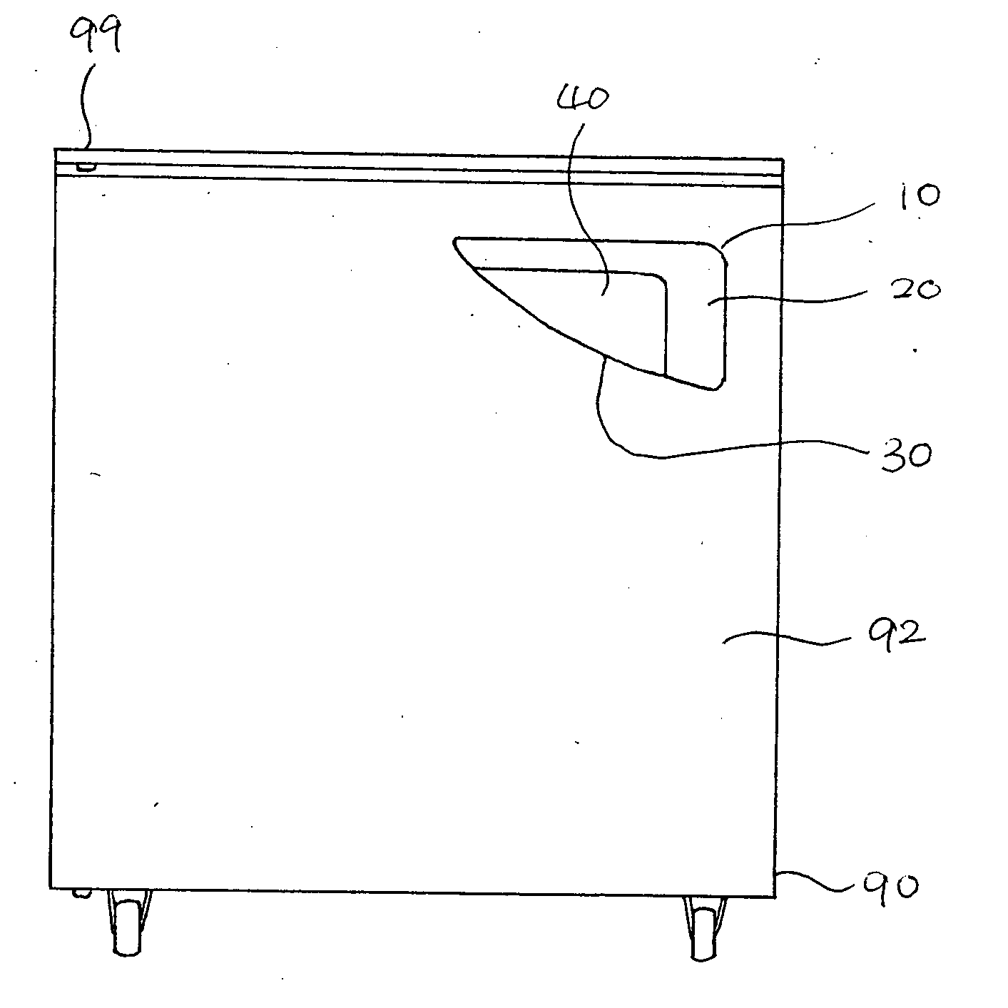
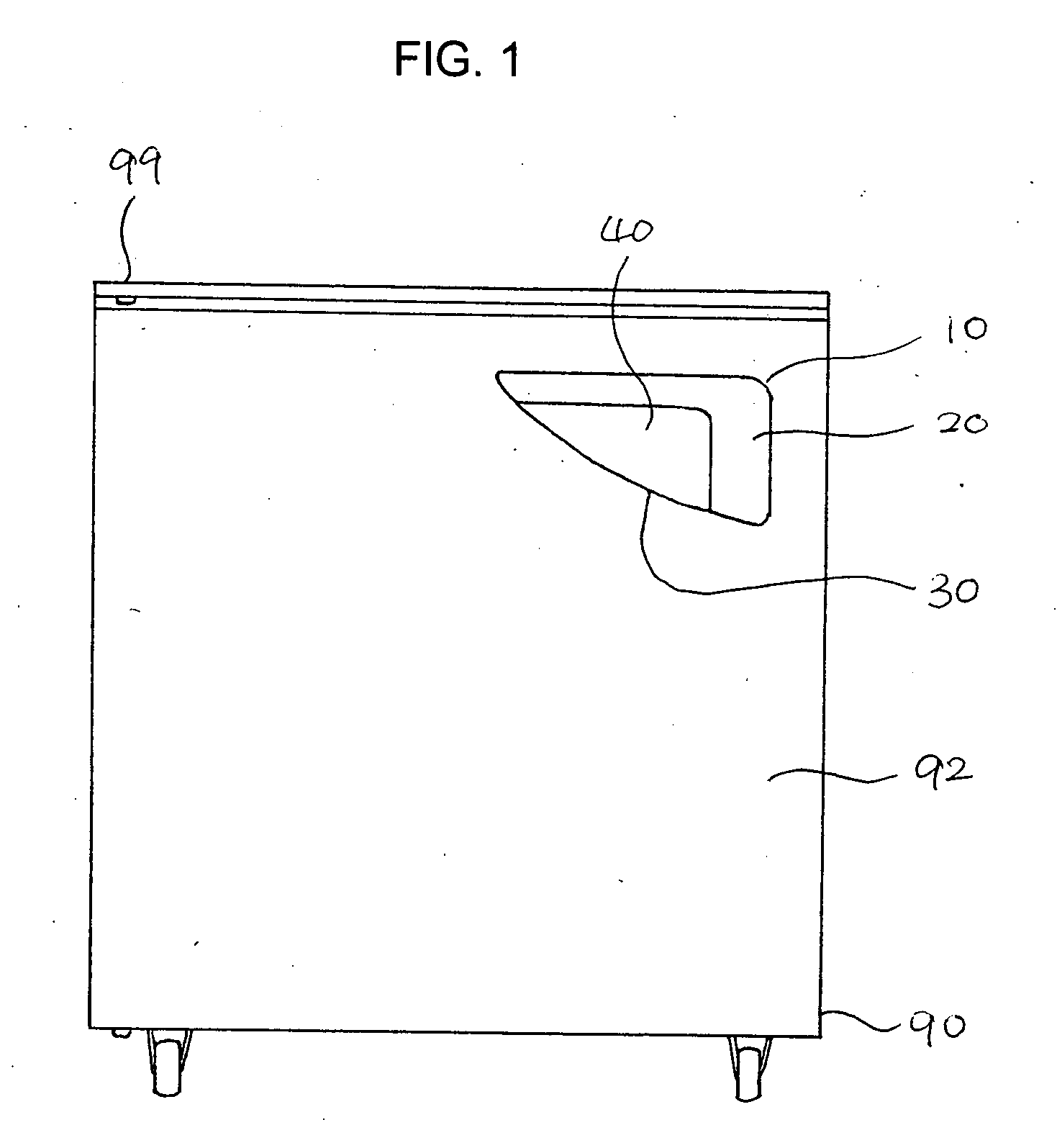
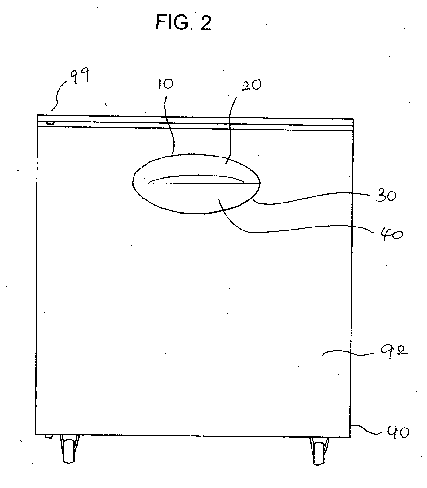
[0032]FIGS. 1 through 4 show door handles with different shapes according to the present invention.

[0033] A door handle 10 for refrigerators and kitchen units 90 includes a base plate 30 and a lip plate 20.

[0034] The base plate 30 has a front surface 32, a rear surface 34, and an edge 36 connecting the front and rear surfaces 32, 34 (refer to FIG. 8 and FIG. 9).

[0035] The lip plate 20 has a top surface 22, a bottom surface 24, and an edge 26 connecting the top and bottom surfaces 22, 24, a coated portion 28 fixed on the top surface 22 of the lip plate 20.

[0036] A part of the edge 36 of the base plate 30 is adjacent to a part of the edge 26 of the lip plate 20, and a gap 40 is provided between the front surface 32 of the base plate 30 and the bottom surface 24 of the lip plate 20 as shown clearly in FIG. 9.

[0037] The lip plate 20 partly covers the base plate 30 allowing a hand to access the gap 40 provided between the front surface 32 of the base plate 30 and the bottom surface ...


PUM


Abstract

A door handle includes a base plate and a lip plate. The base plate has a front surface, a rear surface, and an edge connecting the front and rear surfaces, and the lip plate has a top surface, a bottom surface, an edge connecting the top and bottom surfaces, and a coated portion fixed on the top surface. A part of the edge of the base plate is adjacent to a part of the edge of the lip plate, and a gap is provided between the front surface of the base plate and the bottom surface of the lip plate. The lip plate partly covers the base plate allowing a hand to access the gap provided between the base plate and the lip plate. The base plate is integrated with the door of the refrigerators or the kitchen units. The door handle is substantially right triangular, rectangular, or circular.

Description

BACKGROUND OF THE INVENTION [0001] The present invention relates to a door handle for refrigerators and kitchen units. More particularly, this invention relates to a door handle for refrigerators and kitchen units, which facilitates opening of the door handle by optimizing the pulling point to maximize the pulling torque. Also, the invention relates to a door handle for refrigerators and kitchen units, which increases the visibility of the door handle. [0002] A certain amount of volume of space should be isolated or differentiated from the rest of the surrounding space in order to utilize it. The walls or cases work to that effect in refrigerators and kitchen units. That is, a refrigerator controls and keeps the temperature in the isolated space to be lower than the rest of space, and a kitchen unit makes the isolated space more suitable to store the stuffs or to encase some functions. The isolated space, however, should be eventually accessed from outside by a user. The door of the...

Claims


Application Information

Patent Timeline
Patent Type & Authority Applications(United States)
IPC IPC(8): E05B1/00
CPCE05B1/0015Y10T16/458F25D23/028
Inventor KIM, BRIAN S.
Owner KIM BRIAN S
Why Eureka
Try Eureka