Closetool exhauster with an air dividing case
a technology of exhauster and water closet, which is applied in the direction of water installations, lavatory sanitory, construction, etc., can solve the problems of affecting the health of men, contaminated surroundings, unpleasant odor of air in the toilet, etc., and achieves the effect of reducing costs, venting and keeping the air in the toilet brisk
- Summary
- Abstract
- Description
- Claims
- Application Information
AI Technical Summary
Benefits of technology
Problems solved by technology
Method used
Image

Examples
embodiment 1
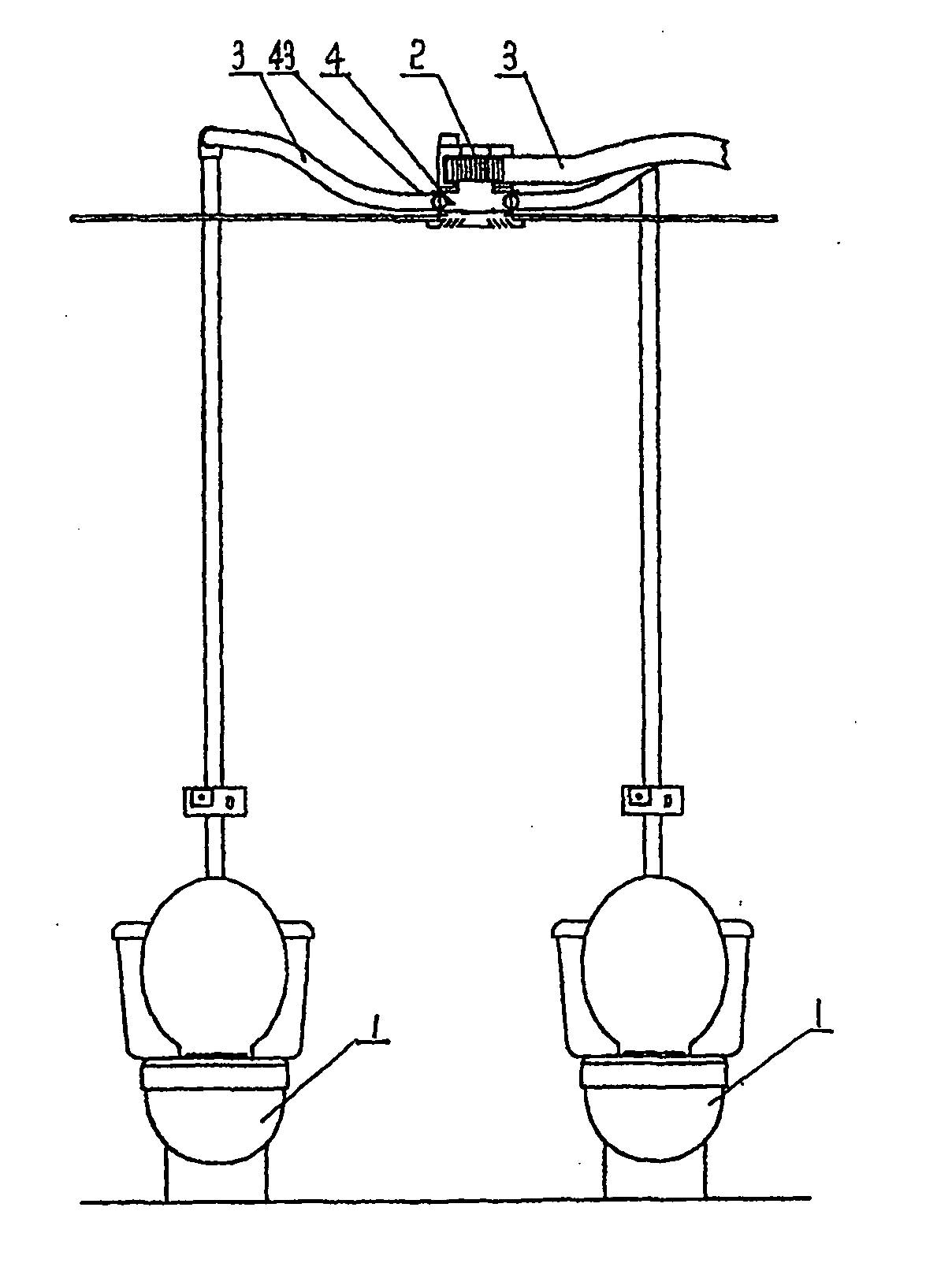
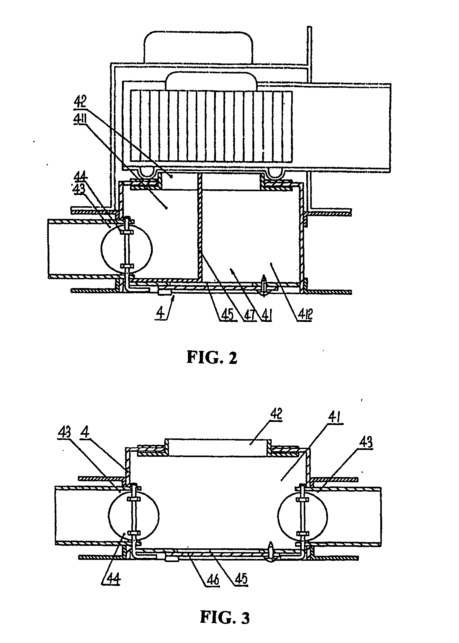
[0021] As shown in FIG. 1 and FIG. 3, exhausting apparatus with an air dividing case for water closet in this invention comprises water closet 1, exhaust fan 2, conducts 3, and air dividing case 4. The air dividing case 4 is provided with an inner chamber 41 wherein there are outlet 42 and two inlets 43 at two sides of the air dividing case 4. The outlet 42 is connected to the inlet of exhaust fan 2 through a conduct 3, while the inlets is connected to two water closets through a conduct 3 respectively. The inlet 43 connects to the inner chamber 41 with adjustable air valves 44 provided between the inlet 43 and inner chamber 41. The adjustable air valve 44 is fixed on pivots and may rotate with its pivot. There is a through hole 45 to toilet on the bottom of inner chamber 41 of air dividing case 4. Through the hole 45 is provided with a movable lid 46 to adjust venting amount. Adjusting this movable lid may control incoming air amount from through the hole 45. The outlet of exhaust ...
embodiment 2
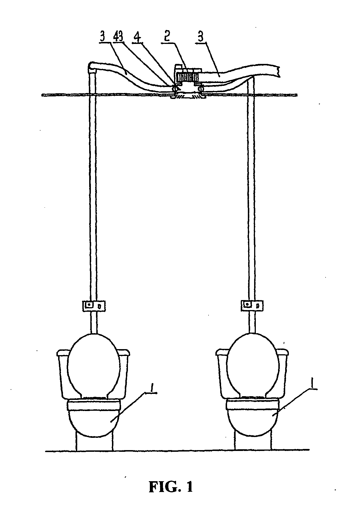
[0022] As shown in FIG. 2, it is basically the same as the embodiment 1 with following exception: there is only one inlet 43 provided in the inner chamber 41, while the inner chamber 41 is provided with an air separate plate 47 which divides the inner chamber 41 into two chambers that does not interlinked each other, namely one chamber to the water closet 411 and another chamber to the room 412. The chamber to the water closet 411 is located at the side of inlet 43, which is connected to the water closet 1 through the conduct 3. The chamber to the room 412 has at its bottom a through hole 45 toward to the toilet. Connection of this embodiment is the same as in embodiment 1, but it can be used for one water closet or toilet only.
embodiment 3
[0023] As shown in FIG. 4, it is basically the same as embodiment 1 with following exception: there are three inlets 43 provided in the inner chamber 41 of air dividing case 4, one of which is located at one side of the air dividing case 4 and other two of which are located at another side of the air dividing case 4. Connection in this embodiment is the same as in embodiment 1, but it can be used for three water closets or toilets.
PUM
 Abstract
Description
Claims
Application Information
 - R&D
- Intellectual Property
- Life Sciences
- Materials
- Tech Scout
- Unparalleled Data Quality
- Higher Quality Content
- 60% Fewer Hallucinations
Browse by: Latest US Patents, China's latest patents, Technical Efficacy Thesaurus, Application Domain, Technology Topic, Popular Technical Reports.
© 2025 PatSnap. All rights reserved.Legal|Privacy policy|Modern Slavery Act Transparency Statement|Sitemap|About US| Contact US: help@patsnap.com