Massaging foot bath

a foot bath and foot bath technology, applied in baths, physical therapy, construction, etc., can solve the problems of decreasing the massaging effect, sanitary problems, and decreasing the strength of water beams, so as to facilitate the user's foot bathing and enhance the sanitary effect of the foot bath. , the effect of enhancing the lifetime of the air pump

Inactive Publication Date: 2006-12-28
CHANG HORNG JIUN
View PDF4 Cites 8 Cited by
  • Summary
  • Abstract
  • Description
  • Claims
  • Application Information

AI Technical Summary

Benefits of technology

[0008] Another objective of the present invention is to provide a foot bath that is operated in a pneumatic manner to produce pressurized air bubbles in the water contained in the receiving chamber to touch and massage the feet of a user, thereby providing a massaging effect to the user's feet.
[0009] A further objective of the present invention is to provide a foot bath, wherein the receiving chamber and the drain hole of the main body are kept at a dry state by the ventilating effect of the air holes of the air guide cushion after use of the foot bath, so that the foot bath is maintained at dry and clean situation, thereby enhancing the sanitary effect of the foot bath, and thereby facilitating the user employing the foot bath.
[0010] A further objective of the present invention is to provide a foot bath, wherein the anti-reverse valve prevents the water contained in the air guide cushion from entering the air pipe and the air pump, thereby enhancing the lifetime of the air pump.

Problems solved by technology

However, the dirt contained in the water easily blocks the water inlet ports and the water outlet ports during a long-term utilization, thereby greatly decreasing the strength of the water beams.
In addition, the receiving chamber of the main body is wet after use of the foot bath so that bacteria easily exist in the receiving chamber, thereby causing a sanitary problem.
Further, the pipes of the foot bath are built in the main body, so that the pipes cannot be replaced when the dirt blocks the pipes, thereby causing a sanitary problem, and thereby decreasing the massaging effect.

Method used


Image

  • Massaging foot bath
  • Massaging foot bath
  • Massaging foot bath

Examples


Embodiment Construction

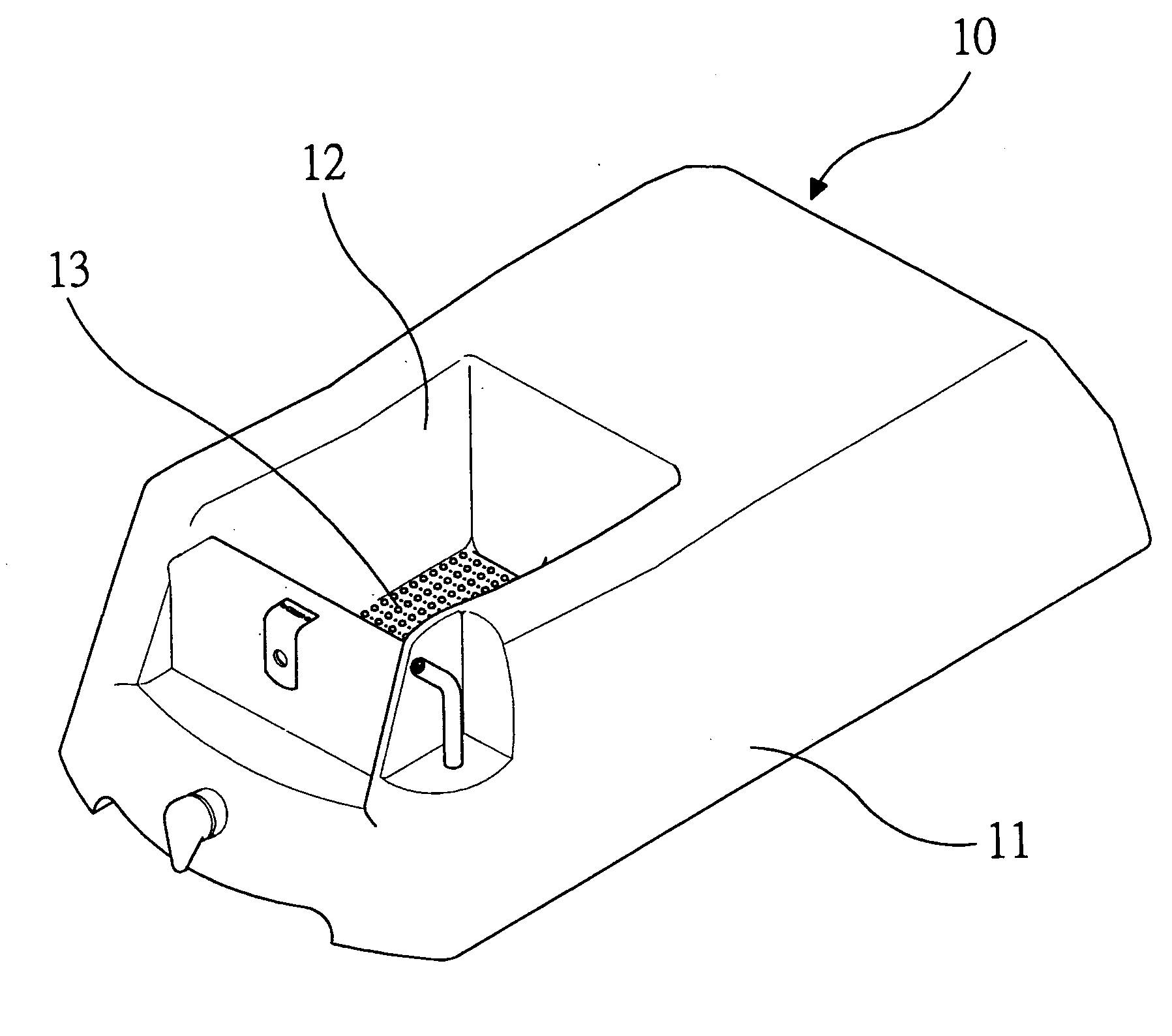
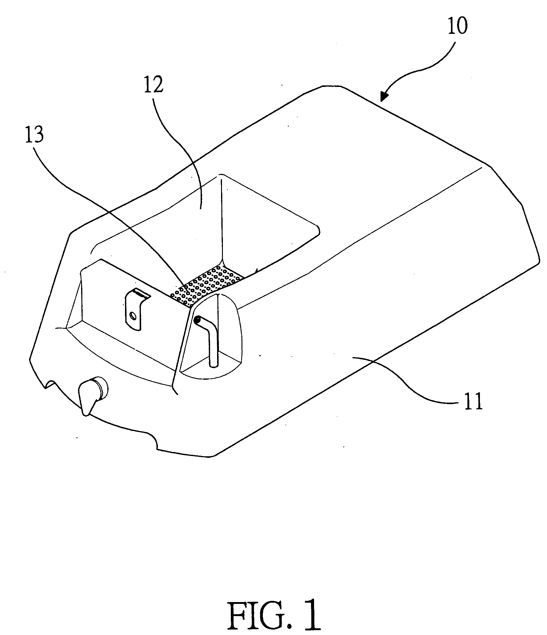
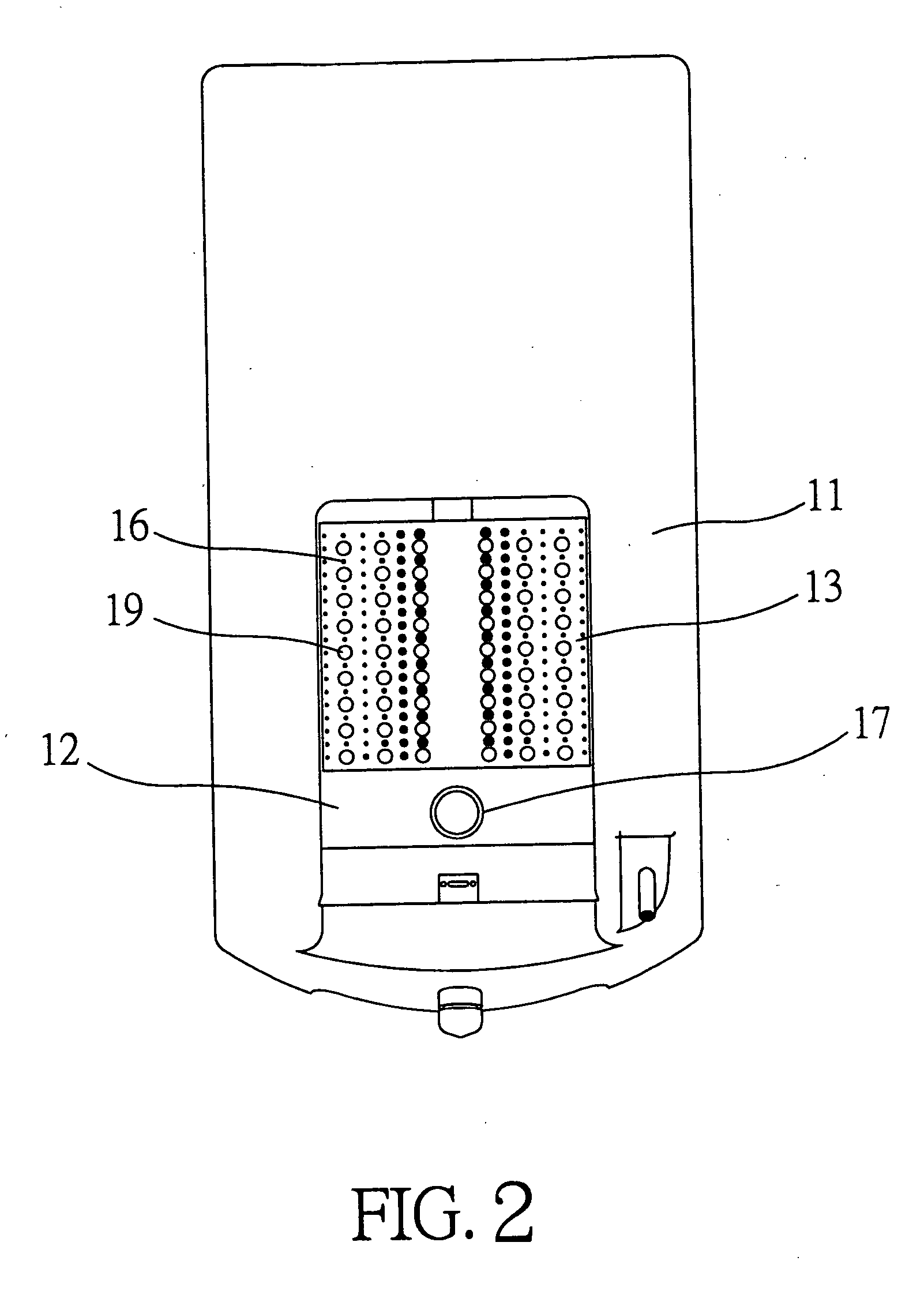
[0018] Referring to the drawings and initially to FIGS. 1-5, a foot bath 10 in accordance with the preferred embodiment of the present invention comprises a main body 11 having a front end formed with a receiving chamber 12 having a side having an upper portion provided with a water inlet valve 18 for filling water with the receiving chamber 12 and having a bottom formed with a drain hole 17 connected to an external pipe 23 to drain the water contained in the receiving chamber 12 outward from the main body 11.

[0019] An air guide cushion 13 is mounted on the bottom of the receiving chamber 12 of the main body 11 and has a substantially arcuate upward protruding side 130. A pneumatic air pump 14 is mounted in the main body 11, and an air pipe 15 is mounted in the main body 11 and connected between the air pump 14 and the air guide cushion 13 to deliver pressurized air from the air pump 14 to the air guide cushion 13. The air pipe 15 has a first end connected to the air pump 14 and a ...


PUM


Abstract

A massaging foot bath includes a main body, an air guide cushion, a pneumatic air pump, and an air pipe. The air guide cushion has a surface formed with a plurality of air holes each connected to the inside of the air guide cushion and the receiving chamber of the main body to deliver the air contained in the inside of the air guide cushion into the receiving chamber. Thus, the foot bath is operated in a pneumatic manner to produce pressurized air bubbles in the water contained in the receiving chamber to touch and massage the feet of a user, thereby providing a massaging effect to the user's feet.

Description

BACKGROUND OF THE INVENTION [0001] 1. Field of the Invention [0002] The present invention relates to a foot bath, and more particularly to a pneumatic massaging foot bath. [0003] 2. Description of the Related Art [0004] A conventional foot bath comprises a main body having a front end formed with a receiving chamber having a side provided with a water inlet valve for filling water with the receiving chamber, a plurality of water inlet ports connected to the receiving chamber to suck the water contained in the receiving chamber, a plurality of water outlet ports connected to the receiving chamber to return the water into the receiving chamber, and a motor mounted in the main body to suck the water contained in the receiving chamber into the water inlet ports and to drain the water through the water outlet ports into the receiving chamber successively so as to form multiple water beams in the receiving chamber, thereby providing a massaging effect to a user's feet. [0005] However, the...

Claims


Application Information

Patent Timeline
Patent Type & Authority Applications(United States)
IPC IPC(8): E03C1/00
CPCA61H33/02A61H35/006A61H33/6068A61H33/6089A61H33/60
Inventor CHANG, HORNG-JIUN
Owner CHANG HORNG JIUN
Why Eureka
Try Eureka