Damper with pressure-sensitive compression damping

a damping and pressure-sensitive technology, applied in the field of dampers, can solve the problems of inability to react, its relative complexity and cost, and blockage of the central passage down the piston rod, and achieve the effect of quick and easy tuning and adjustment, quick and easy

Inactive Publication Date: 2006-12-28
FOX FACTORY
View PDF12 Cites 138 Cited by
  • Summary
  • Abstract
  • Description
  • Claims
  • Application Information

AI Technical Summary

Benefits of technology

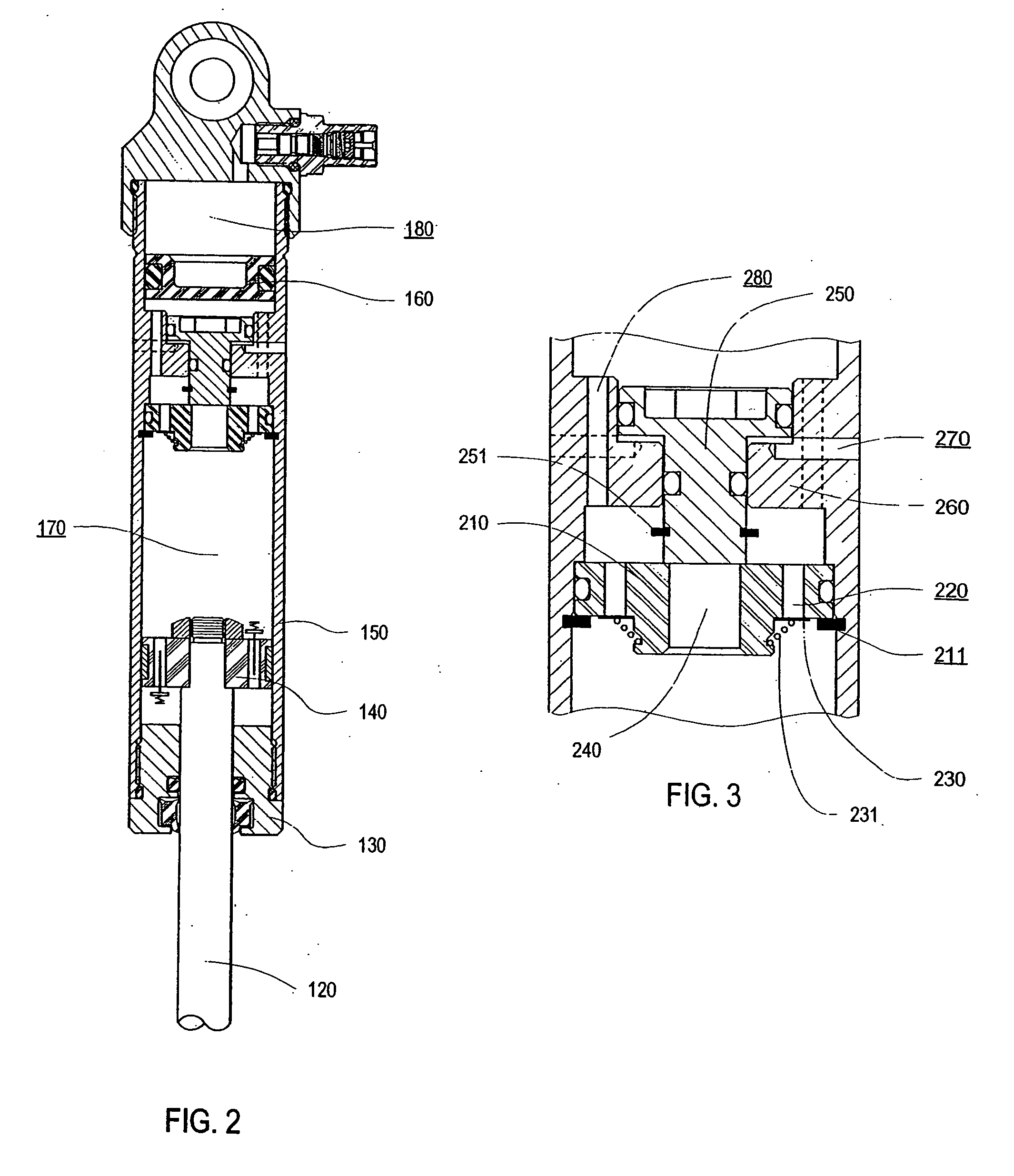
[0020] Another aspect of a preferred embodiment of the present invention is to provide a damper that enables the advantages disclosed to be directly utilized in conjunction with a wide variety of known piston constructions with known characteristics and damping curves, as are known and established in the art for various applications, without substantial alteration to these known piston constructions. Additionally, an aspect is to enable said damper to also utilize the external adjustment features of these known prior art dampers, generally without alteration or re-engineering of said external adjustment features.
[0021] Another aspect of a preferred embodiment of the present invention is to provide a damper where the disclosed damping features can be quickly and easily tuned and adjusted by simply rotating one or more readily-accessible external knobs or levers. In the context of mountain biking applications, for example, those prior-art methods that require an air pressure pump and gauge to alter damping characteristics create a significant interruption in the ride, and thus typically are not done during a ride. In contrast, turning an external knob (or knobs) as described according to the present invention is quick and easy and thus can be done in a routine “on-the-fly” manner frequently during the ride. Since terrain and trail conditions constantly change, this greatly benefits the rider by enabling him / her to continuously select the best damping characteristics for the current situation.

Problems solved by technology

One drawback of this construction is that it is only capable of reacting to one specific condition, the application of the vehicle brakes.
Drawbacks of this construction include its relative complexity and cost, as well as blocked availability to the central passage down the piston rod, which could otherwise be utilized for inclusion of alternate pre-set adjustment mechanisms in communication with the damping piston.
One drawback of this construction is that it produces a relatively “flat” force vs. velocity compression damping curve (a “blow-off” type of damping characteristic), which can be difficult to tune for specific applications and conditions.

Method used


Image

  • Damper with pressure-sensitive compression damping
  • Damper with pressure-sensitive compression damping
  • Damper with pressure-sensitive compression damping

Examples


Embodiment Construction

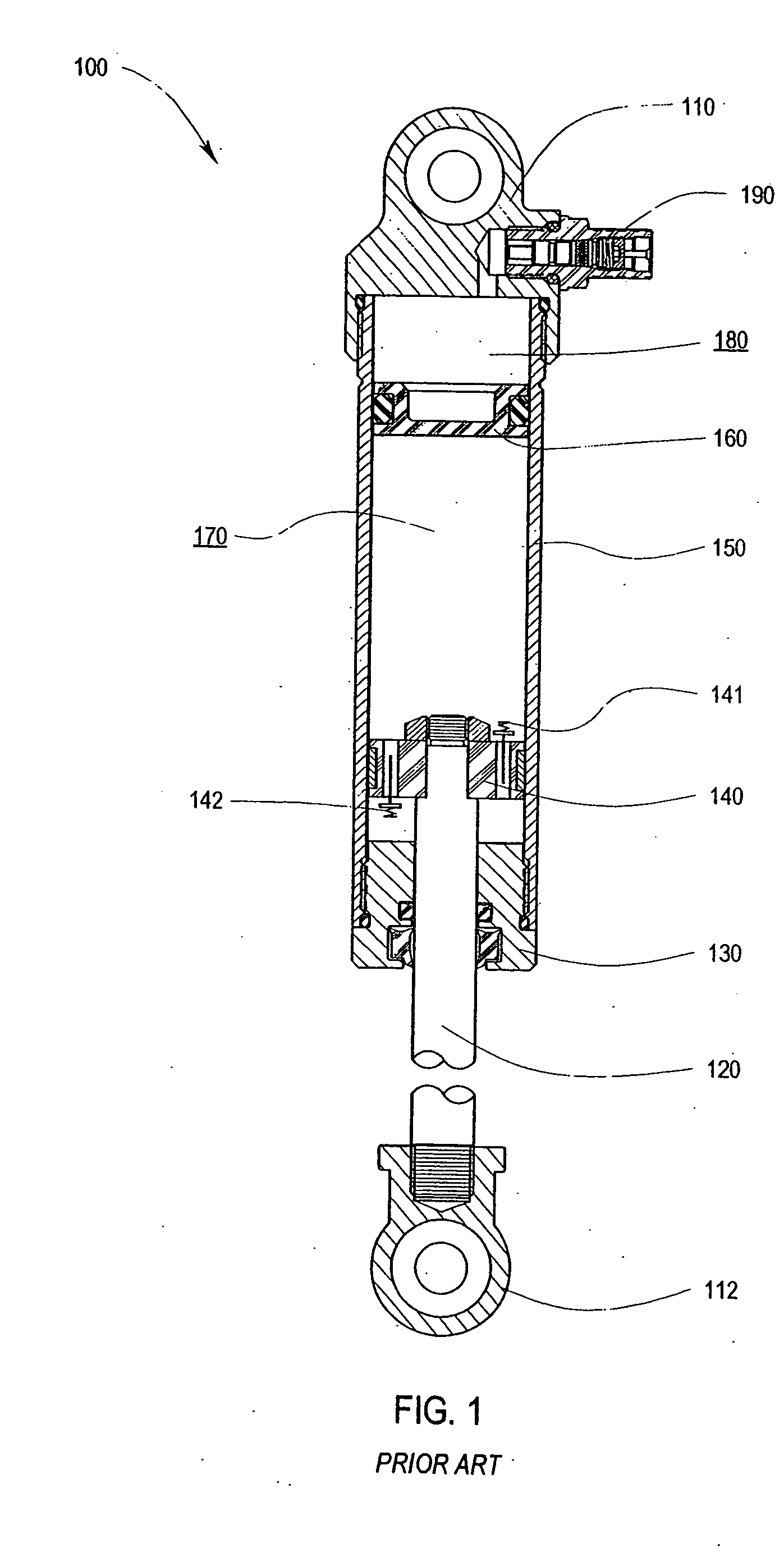
[0062] The prior-art damper 100 of FIG. 1 will be described first, in order to provide a point of departure for better understanding the improvements of the present invention, which will be described further on. It is to be understood, of course, that this specific prior-art embodiment is representative only, and that the embodiments disclosed herein may be applied to other types of dampers.

[0063] In FIG. 1 the prior-art damper 100, as is known to those skilled in the art, is comprised of an upper eyelet 110 and a lower eyelet 112 for attachment to, for example, the sprung and un-sprung portions of a vehicle (not shown). The lower eyelet 112 is connected to the piston rod 120 which passes through the seal head 130 and has a damping piston 140 attached at the other end. The damping piston 140 reciprocates in the damper cylinder 150 as the sprung and unsprung portions of the vehicle move relative to each other when, for example, the vehicle traverses uneven terrain. The damping pisto...


PUM


Abstract

A damper includes a piston rod, a damping piston, at least one cylinder containing a damping liquid, a fixed partition member for partitioning the interior of the damper into two liquid chambers, a pressure source, and a valve in communication with the pressure source which reacts as a function of the pressure. The valve can also be in communication with additional forces, such as mechanical spring forces, which can be adjustable. The valve can include a pressure intensifier. The valve generates fluid flow resistance during flow of liquid in a first direction through the partition member. The fluid flow resistance in the first direction varies according to the amount of force communicated to the valve by the pressure source and any additional forces. The partition member can include means for providing low-resistance return flow of liquid in a second direction.

Description

RELATED APPLICATIONS [0001] This application is a continuation of International Application No. PCT / US2004 / 038661, filed 18 Nov. 2004, which is a continuation of U.S. application Ser. No. 10 / 661,334, filed 12 Sep. 2003, which claims priority to Provisional Application No. 60 / 485,485, filed 8 Jul. 2003, the entireties of which are hereby incorporated by reference herein and made a part of this specification.BACKGROUND OF INVENTION [0002] 1. Field of Invention [0003] This invention relates to a damper and, more particularly, to a damper suitably used as a shock absorber or front fork on the suspension of a bicycle, motorcycle, automobile or other vehicle. [0004] 2. Description of Related Art [0005] Dampers (shock absorbers, MacPherson struts, front forks, etc.) for controlling vehicle body motion and handling characteristics during vehicle travel over uneven surface are well-known in the art. Dampers typically comprise a closed hydraulic cylinder with an internal piston connected to a...

Claims


Application Information

Patent Timeline
Patent Type & Authority Applications(United States)
IPC IPC(8): F16F9/00
CPCF16F9/512F16F9/44F16F9/5126
Inventor FOX, ROBERT C.
Owner FOX FACTORY
Why Eureka
Try Eureka