Method of constructing bumper incorporating thermoformed energy absorber

a technology of thermoplastic energy absorbers and bumpers, which is applied in the direction of bumpers, vehicle components, vehicular safety arrangements, etc., can solve the problems of insufficient realization of unexpected surprises by skilled artisans in bumper design, the cost of energy absorbers, and the cost of tooling and machine time can be significant, so as to achieve quick and easy tuning and optimize energy absorption properties

Inactive Publication Date: 2006-12-21
NETABHAPE ENERGY MANAGEMENT
View PDF99 Cites 12 Cited by
  • Summary
  • Abstract
  • Description
  • Claims
  • Application Information

AI Technical Summary

Benefits of technology

[0011] In still another aspect of the present invention, a method of tuning an inpact-absorbing system to have optimized energy absorption properties upon impact, includes steps of providing a beam assembly including a structural beam, and providing a first sheet of material having known first properties and a first thickness. The method further includes thermoforming a first energy absorber from the first sheet of material, the first energy absorber being constructed to fit against a face of the beam assembly and being configured to support an aesthetic cover. The method further includes providing a second sheet of material different from the first sheet of material in at least one of properties or thickness, and thermoforming a second energy absorber from the second sheet of material, the second energy absorber having different energy absorption characteristics. The method still further includes assembling the first and second energy absorbers at separate times to a beam assembly as part of tuning the system to have a desired rate of energy absorption, whereby the energy absorption of the system can be quickly and easily tuned late in a vehicle development program.

Problems solved by technology

Further, most injection-molded energy absorbers made of solid polymer are relatively complex parts with undulating surfaces, varied wall thicknesses, and different wall spacings to provide optimal energy absorption in different regions of the energy absorbers.
Skilled artisans in bumper design have apparently not fully realized the unexpected added benefits that thermoformed parts can offer when combined with other energy absorbing systems and components.
The cost of energy absorbers and also the cost of tooling and machine time can be significant.
Sometimes a single energy absorber can be designed to work for two different fascia shapes, but this usually results in some undesirable gap(s) between the energy absorber and the fascia that it is supporting.
This can result in sagging and drooping of the fascia in the area of the gaps due to lack of support, potentially leading to consumer complaints and / or the appearance of poor quality in the bumper system.

Method used


Image

  • Method of constructing bumper incorporating thermoformed energy absorber
  • Method of constructing bumper incorporating thermoformed energy absorber
  • Method of constructing bumper incorporating thermoformed energy absorber

Examples


Embodiment Construction

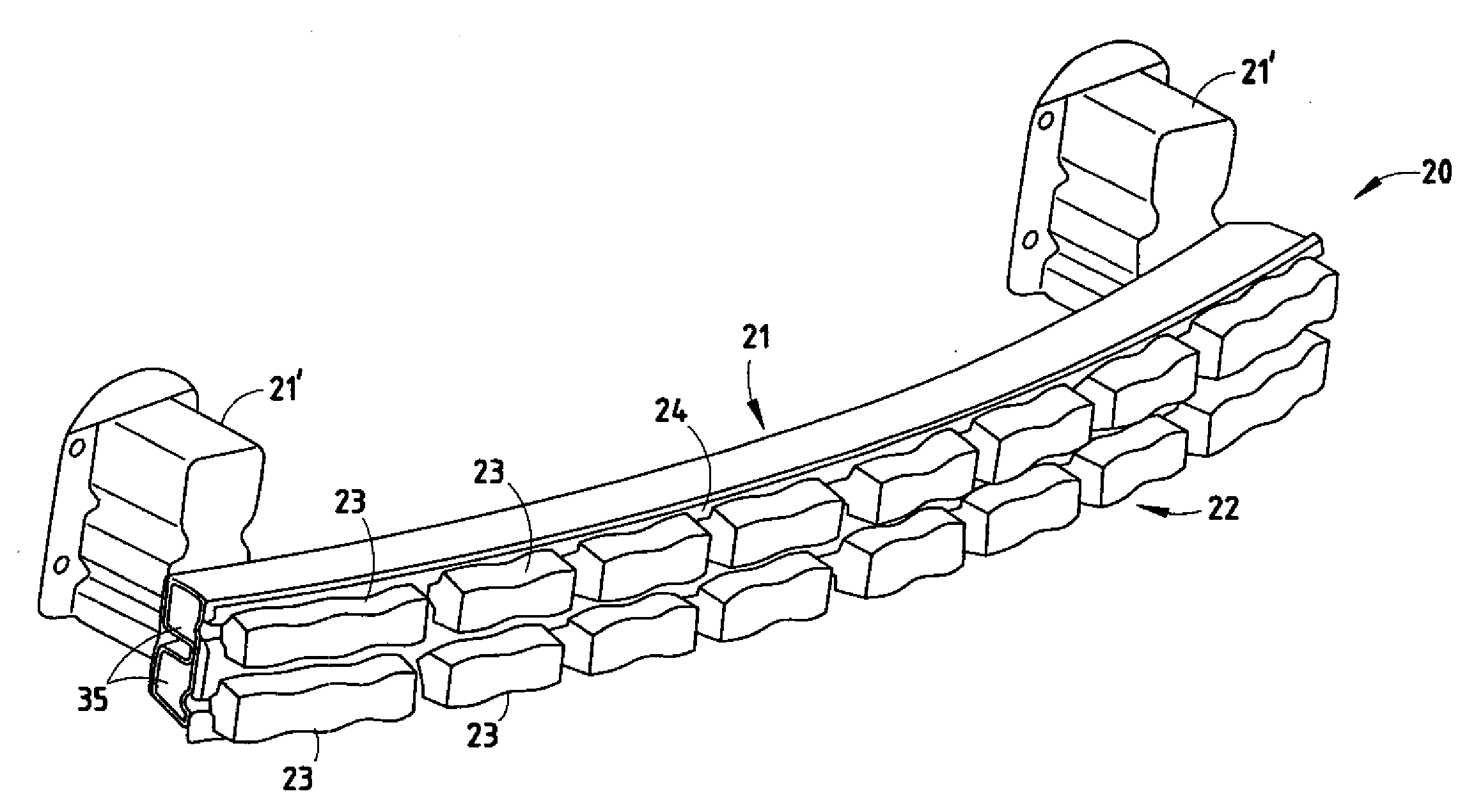
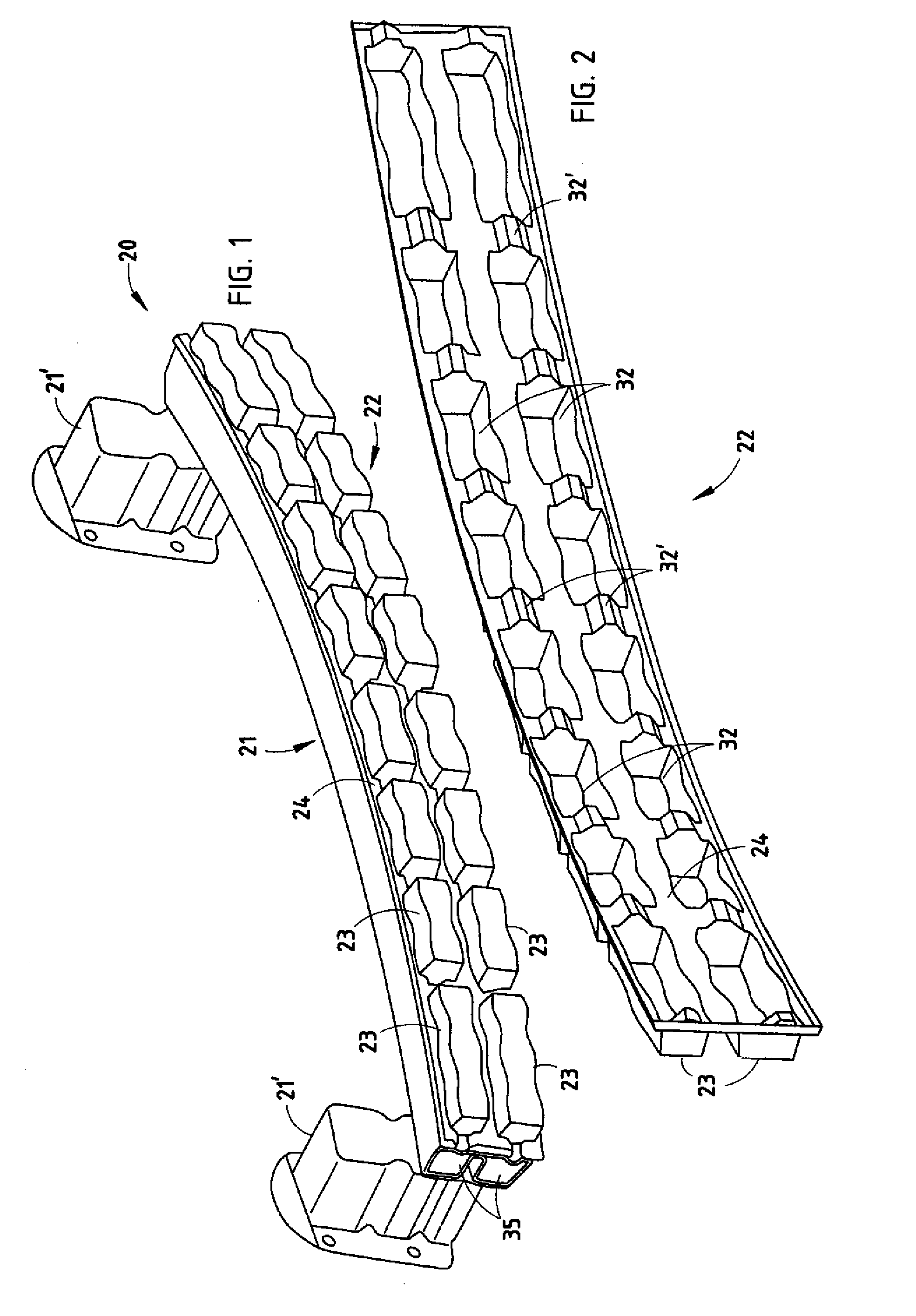
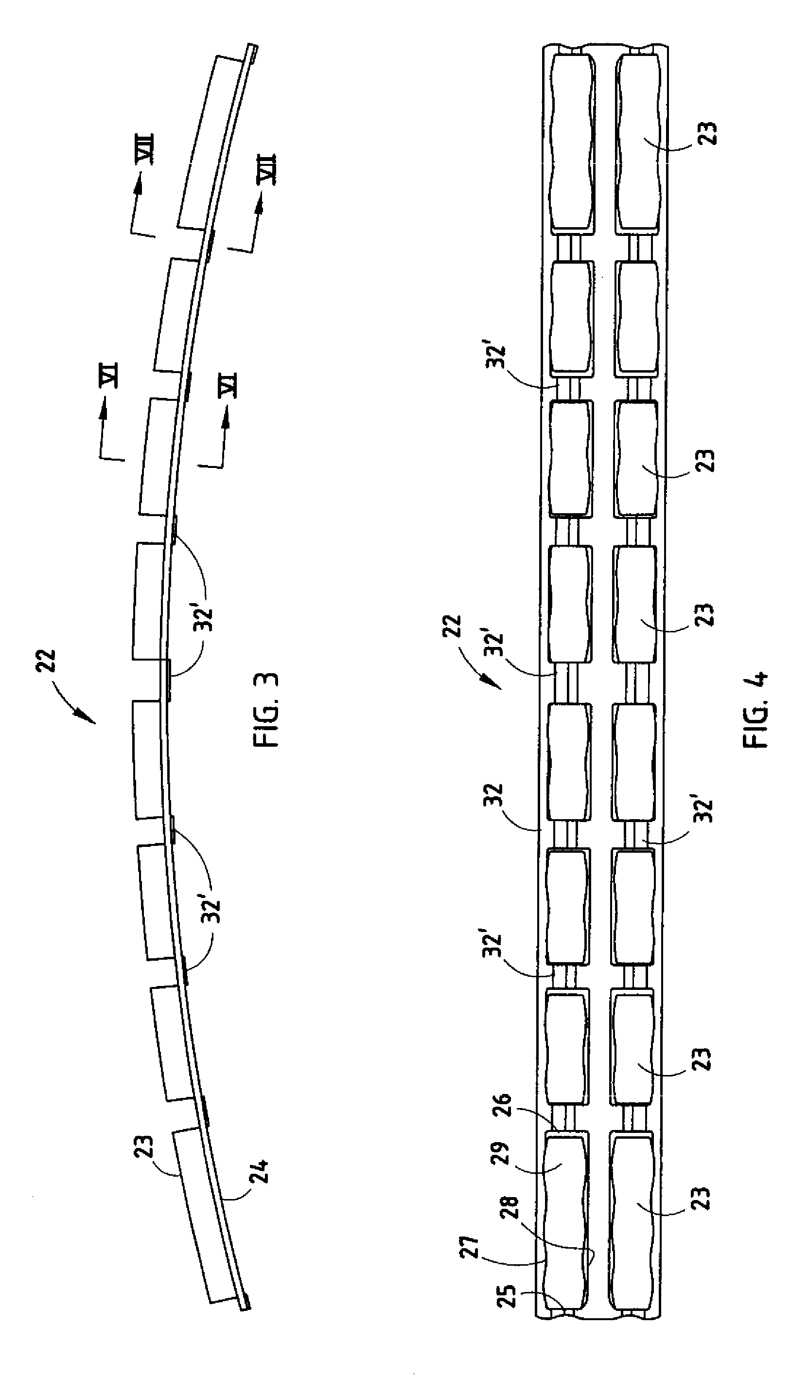
[0043] A bumper system 20 (FIG. 1) includes a B-shaped rollformed and swept tubular beam 21 with mounts 21′ adapted for attachment to front rails of a vehicle frame, and a thermoformed energy absorber 22. The energy absorber 22 has a base flange 24, and a plurality of thermoformed crush boxes 23 thermally deformed from the material of the base flange 24, such as by vacuum forming processes. The crush boxes 23 each have planar energy-absorbing sidewalls 25-28 (FIG. 4) and a face wall 29 to form a box shape with the base-flange-side of the box shape being open. The crush boxes 23 have a thickness (i.e. height) of anywhere from about 10 mm to 60 mm, and more preferably a height of about 20 mm to 30 mm, depending on a space in front of the beam 21 as it sweeps around a front of the vehicle. The vacuum formed energy absorber has a shape chosen to support fascia on the beam 21. It is contemplated that differently shaped energy absorbers 22 can be mated with the same beam 21 to provide fas...


PUM


Abstract

A bumper system includes a tubular beam and a thermoformed energy absorber with crush boxes formed into a base flange, such as by vacuum or thermoforming processes. The crush boxes have planar energy-absorbing sidewalls a depth of about 10 mm to 35 mm, wall thicknesses of about 1 mm to 3 mm, and are formed from polyethylene or other thermoform materials having a memory. The base flange can include thermoformed features engaging recesses in the beam, and is combinable with injection-molded or foam energy absorbers for design flexibility. In one form, the energy absorber includes a thermoformed first sheet forming crush boxes and a second sheet bonded to the first sheet to define apertured air pockets. Related methods of manufacture and impacting are also disclosed.

Description

CROSS REFERENCE TO RELATED APPLICATIONS [0001] This application is a continuation of patent application Ser. No. 10 / 975,743, filed Oct. 28, 2004, entitled BUMPER SYSTEM INCORPORATING THERMOFORMED ENERGY ABSORBER, which is a continuation-in-part of co-assigned PCT application Serial No. PCT / US03 / 39803, filed Dec. 15, 2003, entitled BUMPER SYSTEM INCORPORATING THERMOFORMED ENERGY ABSORBER, which in turn claims benefit of provisional application Ser. No. 60 / 484,712, filed Jul. 3, 2003, entitled BUMPER SYSTEM INCORPORATING THERMOFORMED ENERGY ABSORBER. This application is further a continuation-in-part of and claims benefit of provisional application Ser. No. 60 / 610,492, filed Sep. 16, 2004, entitled BUMPER SYSTEM HAVING THERMOFORMED ENERGY ABSORBER. The entire contents of all aforementioned applications are incorporated herein by reference in their entirety.BACKGROUND OF THE INVENTION [0002] The present invention relates to methods of constructing vehicle bumper systems, and in particu...

Claims


Application Information

Patent Timeline
Patent Type & Authority Applications(United States)
IPC IPC(8): B60R19/03B60R19/18
CPCB60R19/18B60R2019/1833B60R2019/1846Y10T29/49622B60R2019/1866B60R2019/1873B60R2019/186
Inventor EVANS, DARINGUILES, MELVIN
Owner NETABHAPE ENERGY MANAGEMENT
Why Eureka
Try Eureka