Color mixing illumination light unit and system using same

a color mixing and illumination light technology, applied in the field of optical lighting and displays, can solve problems such as particularly high illumination uniformity

Active Publication Date: 2006-12-28
3M INNOVATIVE PROPERTIES CO
View PDF33 Cites 87 Cited by
  • Summary
  • Abstract
  • Description
  • Claims
  • Application Information

AI Technical Summary

Benefits of technology

[0007] Another embodiment of the invention is directed to an illumination light unit that has at least a first light source capable of generating illumination light at a first wavelength and a second light source capable of generating illumination light at a second wavelength different from the first wavelength. The illumination light unit also includes a reflecting cavity having one or more reflectors and a controlled transmission mirror disposed at an output of the reflecting cavity. The controlled transmission mirror includes an input coupling element, an output coupling element and a first multilayer reflector disposed between the input and output coupling elements. At least some of the illumination light from the first and second light sources is reflected within the reflecting cavity by the one or more reflectors and is transmitted out of the reflecting cavity through the controlled transmission mirror.
[0008] The above summary of the present invention is not intended to describe each illustrated embodiment or every implementation of the present invention. The following figures and detailed description more particularly exemplify these embodiments.

Problems solved by technology

Illuminance uniformity is particularly a problem when the light sources used are point sources, for example are light emitting diodes (LEDs).

Method used


Image

  • Color mixing illumination light unit and system using same
  • Color mixing illumination light unit and system using same
  • Color mixing illumination light unit and system using same

Examples


Embodiment Construction

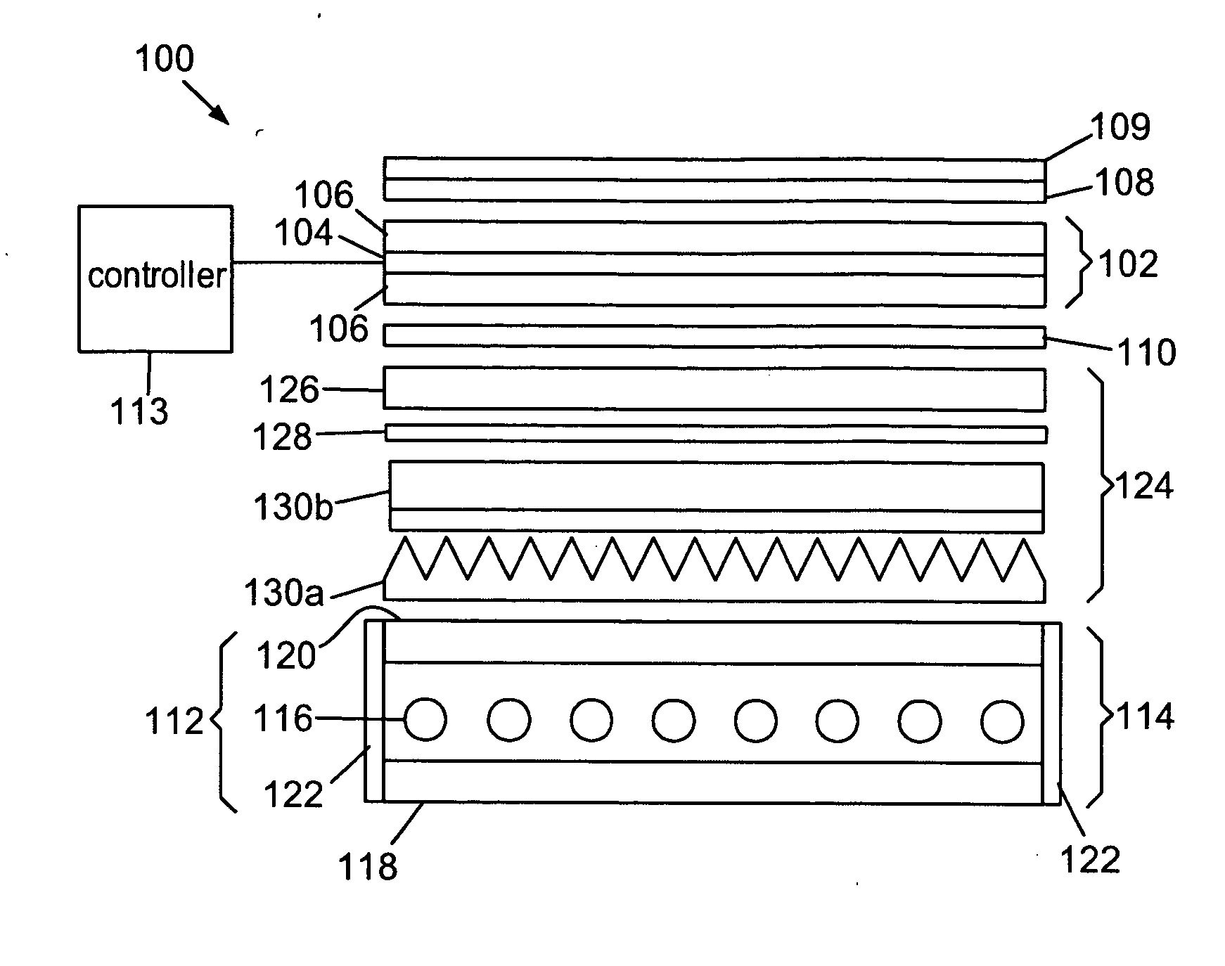
[0025] The present invention is applicable to illuminated signs and displays, such as liquid crystal displays (LCDs, or LC displays), and is applicable to displays that are illuminated using light sources positioned directly behind the display panel, known as direct-lit displays, and to displays that are illuminated using light sources positioned to the side of the display panel, known as edge-lit displays. The invention is believed to be particularly useful for displays that are illuminated by light sources of different colors. The invention is believed also to be applicable to systems that provide space lighting.

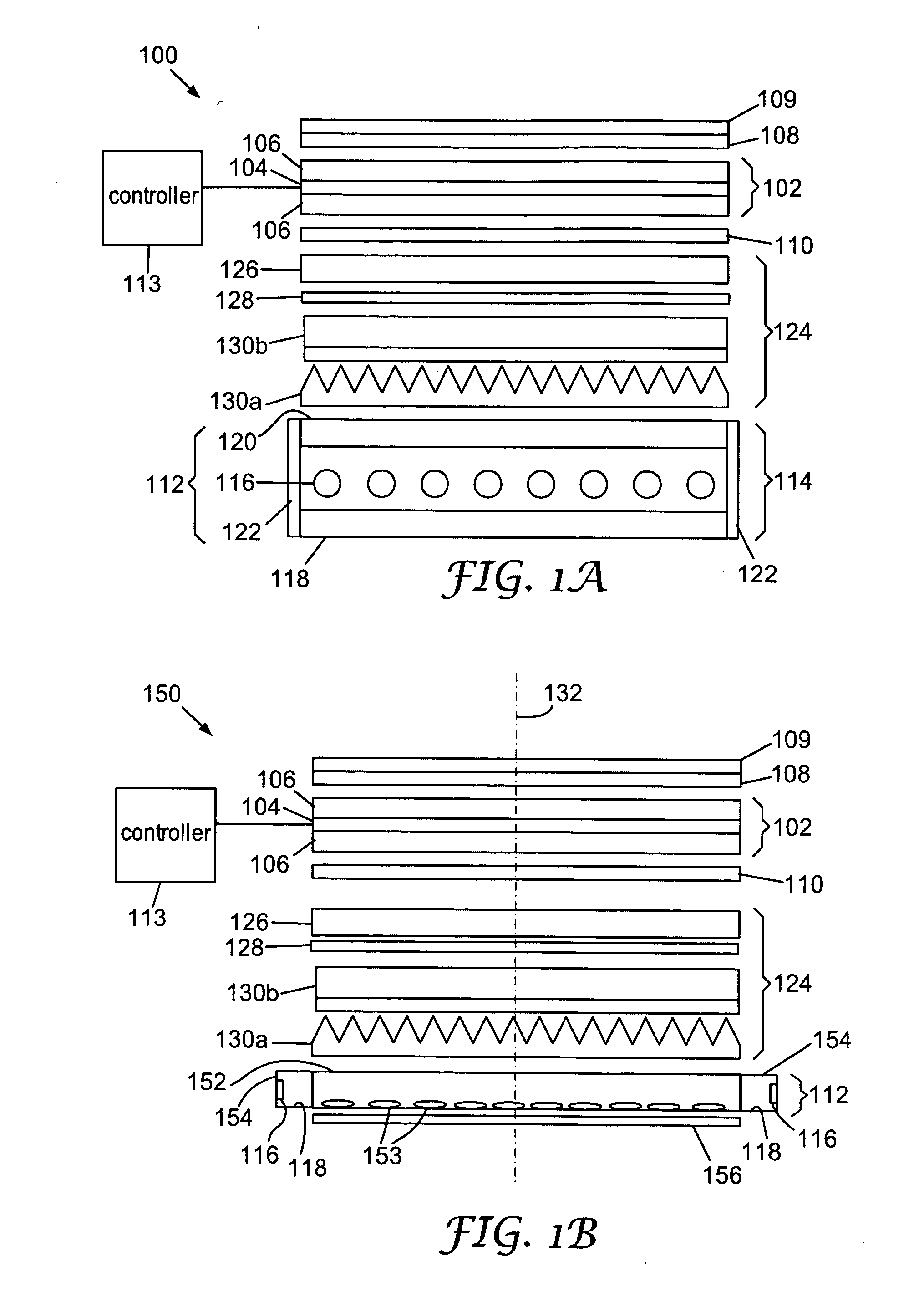
[0026] A schematic exploded view of an exemplary embodiment of a direct-lit display system 100 is presented in FIG. 1A. Such a display system 100 may be used, for example, in an LCD monitor or LCD-TV. In this exemplary embodiment, the device 100 uses a liquid crystal (LC) display panel 102, which typically comprises a layer of LC 104 disposed between panel plates 106. The...


PUM


Abstract

An illumination light unit includes at least two light sources that generate light at different wavelengths. The illumination light unit also includes a reflecting cavity having one or more reflectors and a controlled transmission mirror disposed at an output of the reflecting cavity. The controlled transmission mirror includes an input coupling element, an output coupling element and a first multilayer reflector disposed between the input and output coupling elements. At least some of the light from the light sources is reflected within the reflecting cavity by the one or more reflectors and is mixed. Light passes out of the reflecting cavity through the controlled transmission mirror. The illumination light unit may be used for illumination purposes, or as part of a backlight for illuminating a display.

Description

RELATED APPLICATIONS [0001] This application is related to the following applications, all of which are incorporated herein by reference: U.S. patent application Ser. No. ______, titled “OPTICAL ELEMENT FOR LATERAL LIGHT SPREADING IN BACK-LIT DISPLAYS AND SYSTEM USING SAME”, filed on even date herewith and having attorney docket no. 60499US002; U.S. patent application Ser. No. ______, titled “OPTICAL ELEMENT FOR LATERAL LIGHT SPREADING IN EDGE-LIT DISPLAYS AND SYSTEM USING SAME”, filed on even date herewith and having attorney docket no. 60709US002; U.S. patent application Ser. No. ______, titled “ILLUMINATION ELEMENT AND SYSTEM USING SAME”, filed on even date herewith and having attorney docket no. 60975US002; and U.S. patent application Ser. No. ______, titled “POLARIZATION SENSITIVE ILLUMINATION ELEMENT AND SYSTEM USING SAME”, filed on even date herewith and having attorney docket no. 60976US002.FIELD OF THE INVENTION [0002] The invention relates to optical lighting and displays,...

Claims


Application Information

Patent Timeline
Patent Type & Authority Applications(United States)
IPC IPC(8): F21V7/04
CPCG02B6/0031G02B6/0055G02B6/0068G02B5/0816G02F1/133606G02F2001/133507G02B5/0294G02F1/133603G02F1/133507G02F1/1335
Inventor EPSTEIN, KENNETH A.WEBER, MICHAEL F.
Owner 3M INNOVATIVE PROPERTIES CO
Why Eureka
Try Eureka