Storm protection apparatus

Inactive Publication Date: 2007-01-04
LOGAN EDWARD ALEXANDER
View PDF5 Cites 34 Cited by
  • Summary
  • Abstract
  • Description
  • Claims
  • Application Information

AI Technical Summary

Benefits of technology

[0047] Preferably, the anchor further comprises an adjustable member adjustably mounted on the elongate member and aligned substantially coaxially therewith such that a telescoping effect between the elongate member and adjustable member may be achieved. Accordingly, the length of the anchor may be varied. In a preferred arrangement the adjustable member is threadably coupled to the elongate member such that relative rotation of the adjustable member and elongate member permits adjustment therebetween.
[0048] Advantageously, in use, the toggle element of the anchor may be located in the first position and the anchor subsequently driven into the ground, for example by hammering or the like, with an end of the toggle element leading. A driving rod may be utilised during insertion of the anchor into the ground. For example, the driving rod may engage the toggle element and be adapted to apply or transmit a driving force thereto to drive the anchor into the ground. On

Problems solved by technology

Damage or loss of property, such as permanent buildings, mobile accommodation such as caravans, vehicles, boats ashore, aircraft or the like often occurs during extreme weather conditions where high wind-generated forces exist.
For example, items may be displaced from their intended location if their weight and/or anchorage is insufficient to resist the loads induced by high winds.
However, it is often the case that damage to structures, such as permanent buildings, is initiated at their roof portion due to the creation of adverse pressure differentials.
Moreover, air will be forced into the s

Method used


Image

  • Storm protection apparatus
  • Storm protection apparatus
  • Storm protection apparatus

Examples


Example

DETAILED DESCRIPTION OF THE DRAWINGS

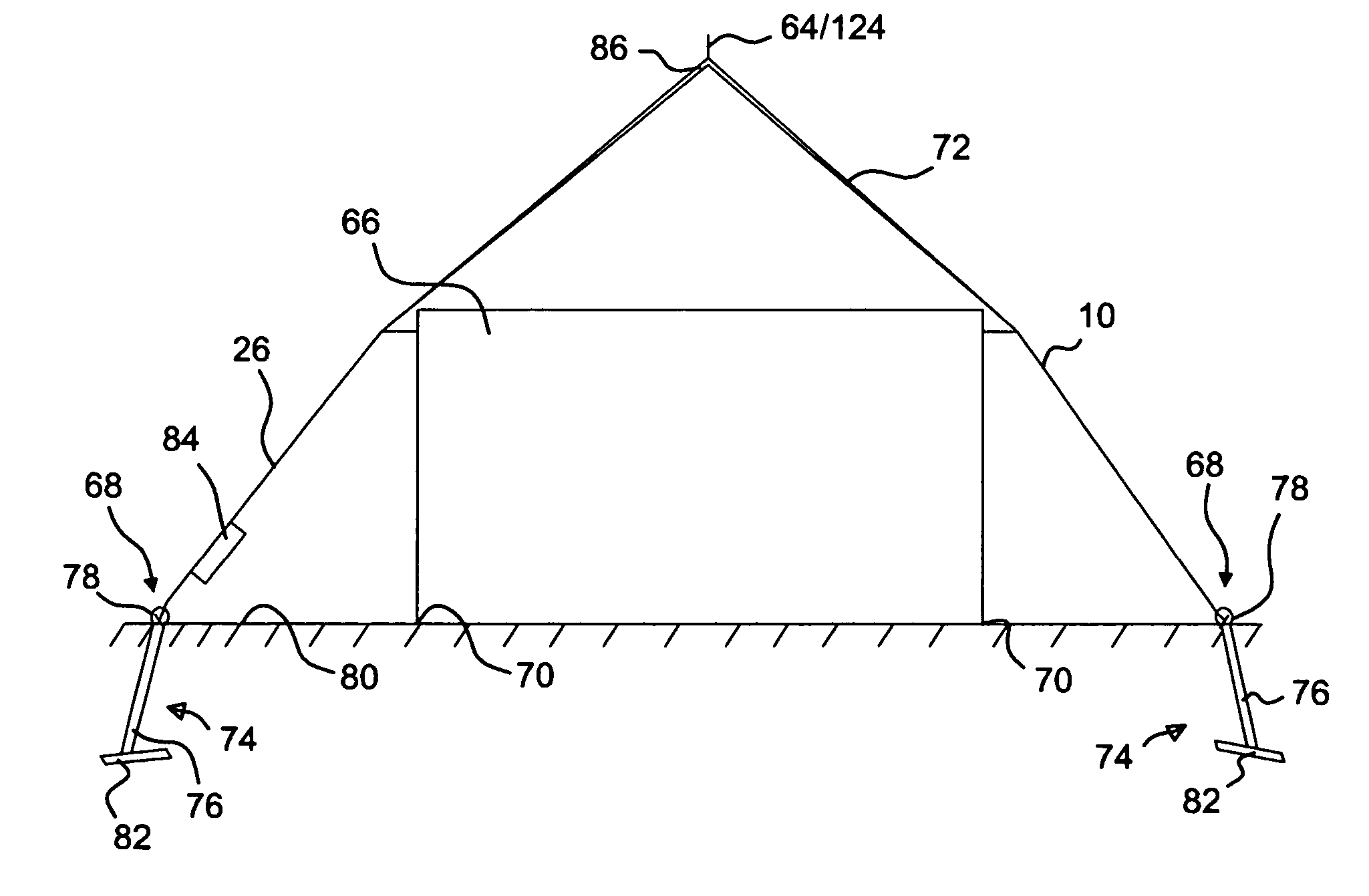
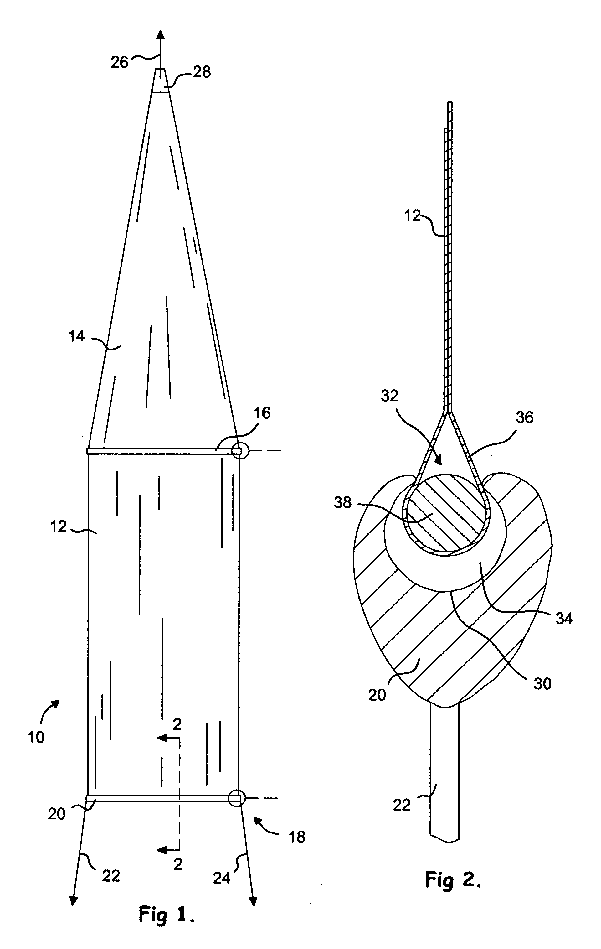
[0086] Reference is first made to FIG. 1 in which there is shown a plan view of an apparatus, generally identified by reference numeral 10, in accordance with an embodiment of the present invention. As will be discussed in more detail below, the apparatus 10 is adapted for use in providing protection to an asset, such as a building or the like from damage which may be caused during high wind conditions.

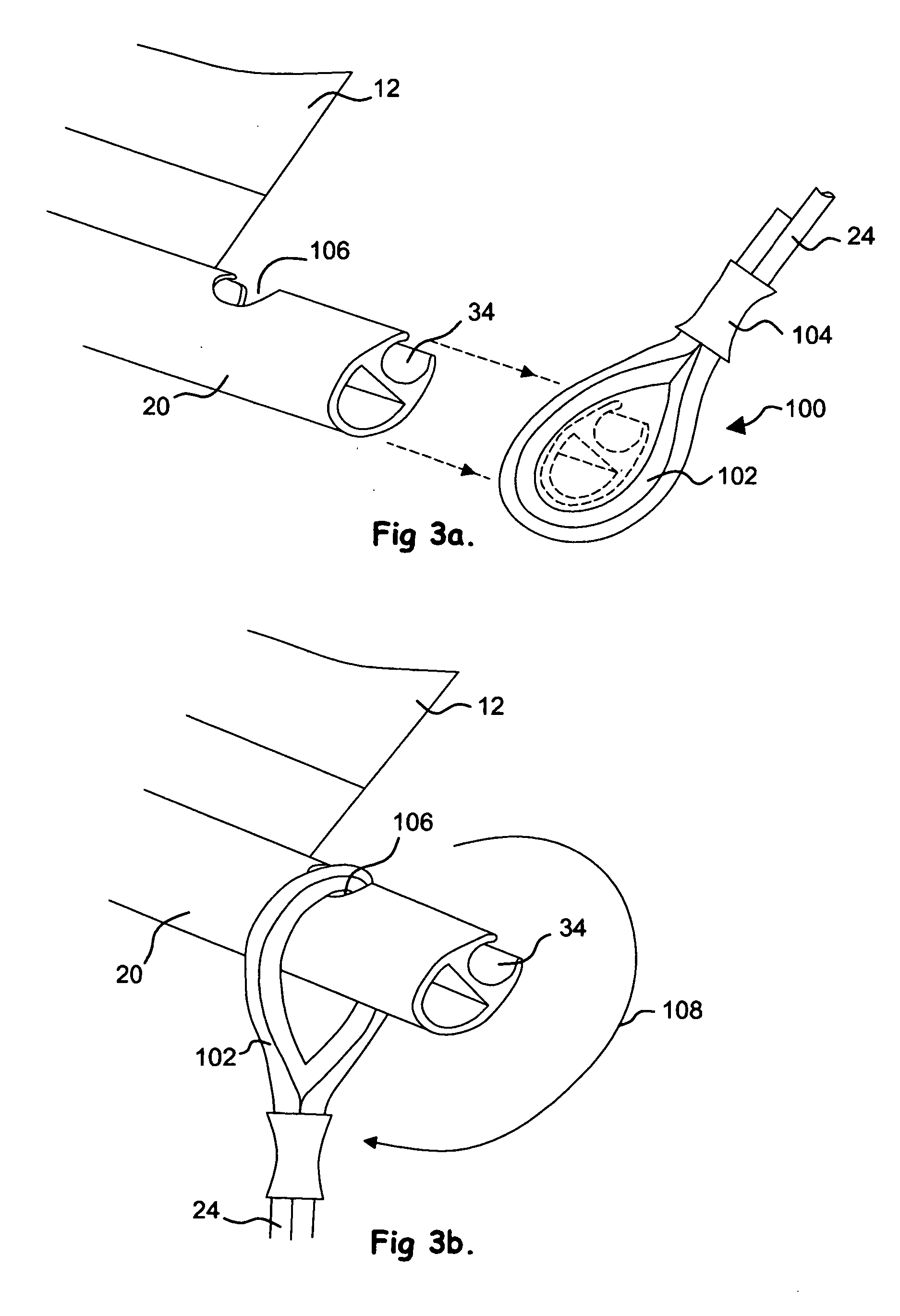
[0087] The apparatus 10 comprises a first flexible sheet member 12 which is generally rectangular in shape, and a second flexible sheet member 14 which is generally triangular in shape, wherein the first and second sheet members 12, 14 are coupled together via a rigid interconnecting member 16. Preferred forms of interconnecting member 16 will be discussed in detail below. The first and second sheet members 12, 14 are composed primarily of a fabric material, such as a woven fabric, non-woven fabric, laminated fabric, composite fabric or the like, ...


PUM


Abstract

An apparatus for use in connecting an asset comprises one or more sheet members adapted to be located over an upper surface of an asset and secured between suitable anchors, preferably secured to the ground. In one disclosed embodiment the apparatus is modular and comprises a plurality of sheets releasably connected together via one or more interconnecting assemblies. In use, the apparatus deflects high winds around and over the asset, thus preventing or reducing damage caused by high wind loading.

Description

CLAIM FOR RIGHT OF PRIORITY UNDER 35 U.S.C. §119(b) [0001] This present application claims all available benefit, under 35 U.S.C. § 119(b), of Utility Patent Application No. GB 0513335.0 filed in the United Kingdom on Jun. 30, 2005. FIELD OF THE INVENTION [0002] The present invention relates to an apparatus for use in protecting assets, such as buildings and the like, from damage caused by extreme weather, particularly high wind conditions. BACKGROUND TO THE INVENTION [0003] Damage or loss of property, such as permanent buildings, mobile accommodation such as caravans, vehicles, boats ashore, aircraft or the like often occurs during extreme weather conditions where high wind-generated forces exist. For example, items may be displaced from their intended location if their weight and / or anchorage is insufficient to resist the loads induced by high winds. However, it is often the case that damage to structures, such as permanent buildings, is initiated at their roof portion due to the ...

Claims


Application Information

Patent Timeline
IPC IPC(8): E04B1/34E02D5/80E04H9/14E04H15/64
CPCE02D5/803E04H15/644E04H9/14Y02A50/00
Inventor LOGAN, EDWARD ALEXANDER
Owner LOGAN EDWARD ALEXANDER
Why Eureka
Try Eureka