Mechanical four position brush chipper feed control bar

a technology of feed control and brush chipper, which is applied in the field of mechanical four-position brush chipper feed control, can solve the problem of less versatility of electrical system

Inactive Publication Date: 2007-01-04
VERMEER MFG CO
View PDF7 Cites 25 Cited by
  • Summary
  • Abstract
  • Description
  • Claims
  • Application Information

AI Technical Summary

Benefits of technology

[0013] Still another object of the present invention is to provide a stop function to the mechanical feed control bar wherein, when the feed control bar is in its stop position, another lever must be manually manipulated in order to return the feed mechanism to a forward feed. This prevents prematurely feeding material into the chipper before the problem has been fully remedied.

Problems solved by technology

Mechanical control systems do not require electrical power, but have proved less versatile than the electrical systems in the past.

Method used


Image

  • Mechanical four position brush chipper feed control bar
  • Mechanical four position brush chipper feed control bar
  • Mechanical four position brush chipper feed control bar

Examples


Embodiment Construction

[0042] For the purposes of this document, the term mechanical control is defined as a control system wherein actuation is due to a mechanical linkage from the control bar to the hydraulic control valve. No electrical actuation is incorporated. Of course merely adding electrical components to the mechanical system of the present invention can be done and still be within the scope and spirit of the present invention.

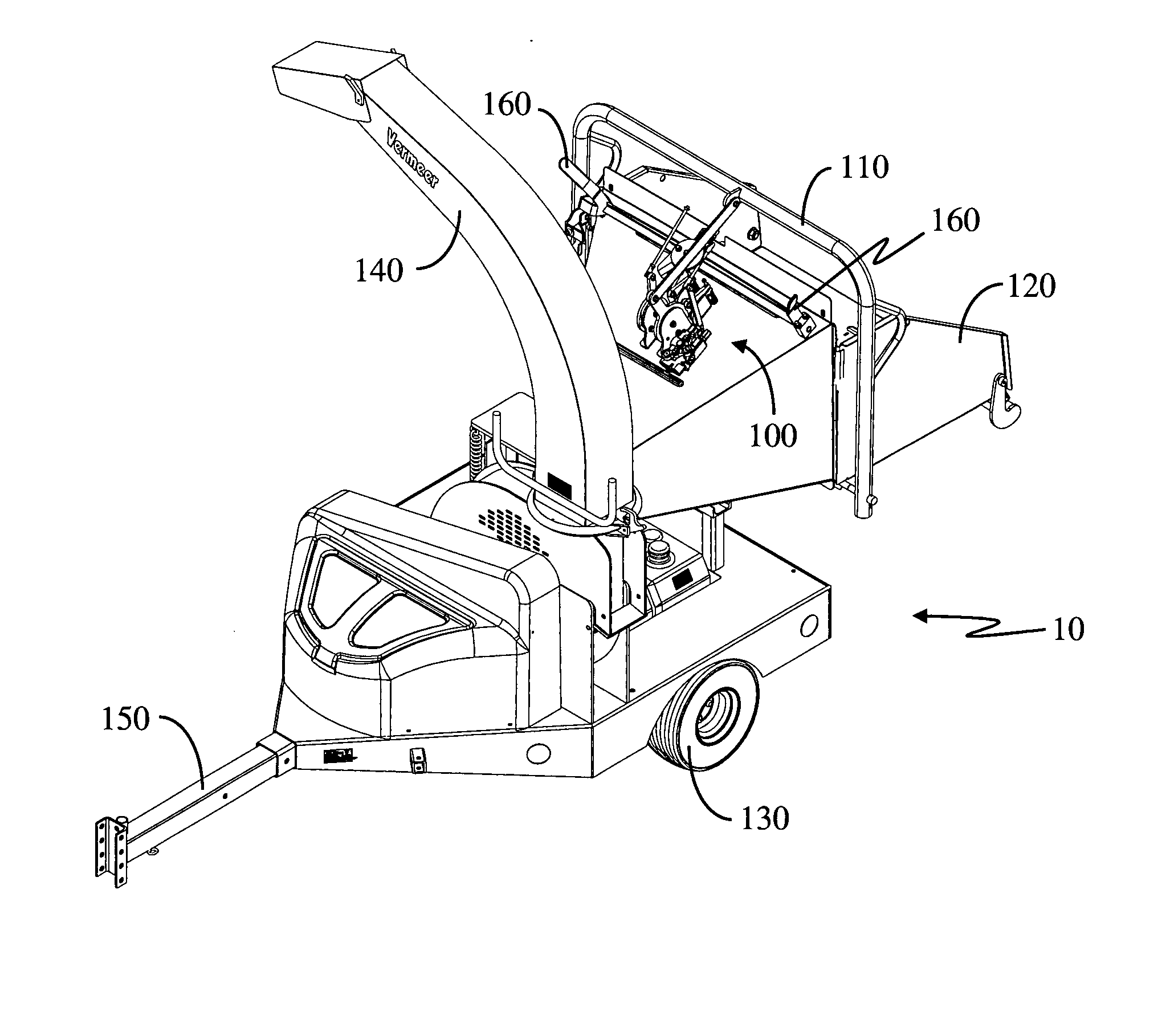
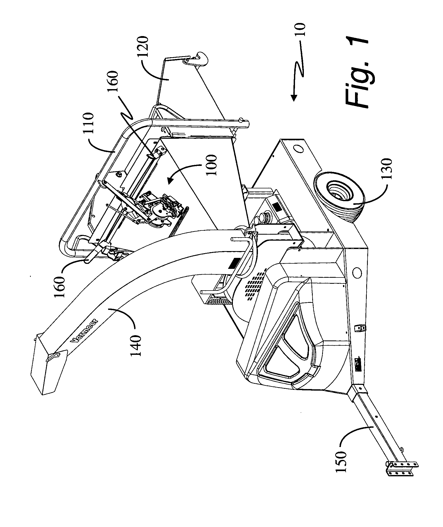
[0043] A brush chipper 10 is shown in FIG. 1. The direction of brush feeding is generally controlled through the manipulation of the feed control assembly 100 via the upper feed control bar 110. Generally, the brush chipper comprises a feed table assembly 120, ground engaging wheels 130 (only one seen in FIG. 1), and a conveyance for chipped matter, in this case a chute 140. Not seen in FIG. 1 are a plurality of feed rollers driven by hydraulic motors, and at least one cutter drum or cutter disk.

[0044] The brush chipper 10 of FIG. 1 has a front, generally toward the tong...


PUM

PropertyMeasurementUnit
tension forceaaaaaaaaaa
compressive forceaaaaaaaaaa
forceaaaaaaaaaa

Abstract

A mechanical control mechanism for the feed of a brush chipper is disclosed. The feed control bar has four positions: (1) forward or feed, (2) neutral, (3) reverse, and (4) stop. The hydraulic control valve has the three usual positions: (1) forward or feed, (2) neutral, (3) reverse. A function of the feed control bar is to provide the three function of the hydraulic control valve, plus the fourth in a fashion amenable to emergency situations. To these ends, the control bar has an extreme rearward position wherein the feed mechanism is stopped. The only permissible change to the stopped condition of the feed mechanism is to reverse the feed. Until a reset lever is manipulated, the hydraulic control valve cannot be put into a forward feed position.

Description

CROSS REFERENCE TO RELATED APPLICATIONS [0001] Not applicable. STATEMENT REGARDING FEDERALLY SPONSORED RESEARCH OR DEVELOPMENT [0002] Not applicable. REFERENCE TO MICROFICHE APPENDIX [0003] Not applicable. BACKGROUND OF THE INVENTION [0004] 1. Field of the Invention [0005] This invention relates to feed control for a brush chipper. More particularly, the invention relates to a method and apparatus for providing a stop position to the forward (or feed), neutral, and reverse positions presently associated with brush chipper mechanical feed bar mechanisms. The hydraulic control valve actuated by the feed bar has three positions: forward (or feed), neutral, and reverse. [0006] 2. Background Art [0007] Feed control for a brush chipper presently takes one of two forms: (1) mechanical or (2) electrical. Electrical controls require a functioning source of electrical power such as a generator or battery. Mechanical control systems do not require electrical power, but have proved less versati...

Claims


Application Information

Patent Timeline
Patent Type & Authority Applications(United States)
IPC IPC(8): B02C25/00
CPCB02C18/2283A01G3/002
Inventor BOUWERS, JOHN T.B.SCHUT, LARRY D.
Owner VERMEER MFG CO
Why Eureka
Try Eureka