Automatic ventilation device for chair

a technology of automatic ventilation and chair, which is applied in the direction of chairs, vehicle components, vehicle arrangements, etc., can solve problems such as user discomfort, and achieve the effect of saving energy and making users comfortabl

Inactive Publication Date: 2007-01-04
LEE HWANG PAO
View PDF7 Cites 6 Cited by
  • Summary
  • Abstract
  • Description
  • Claims
  • Application Information

AI Technical Summary

Benefits of technology

The invention describes a way to make chairs more comfortably by using an air flow system that cools down the user's body. This helps save energy because there is no electricity needed for this process.

Problems solved by technology

The technical problem addressed by this patent is how to provide effective ventilation for car seats and office chairs without requiring external power sources like battery drives.

Method used


Image

  • Automatic ventilation device for chair
  • Automatic ventilation device for chair
  • Automatic ventilation device for chair

Examples


Embodiment Construction

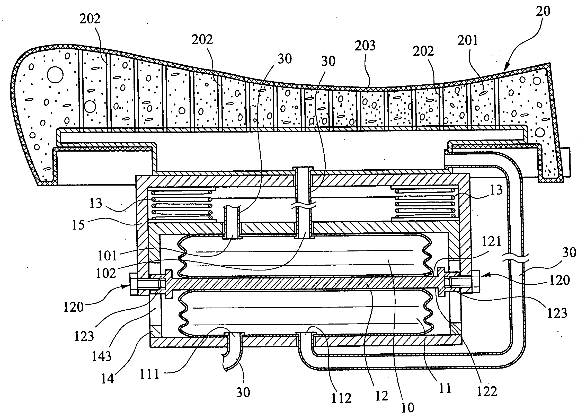
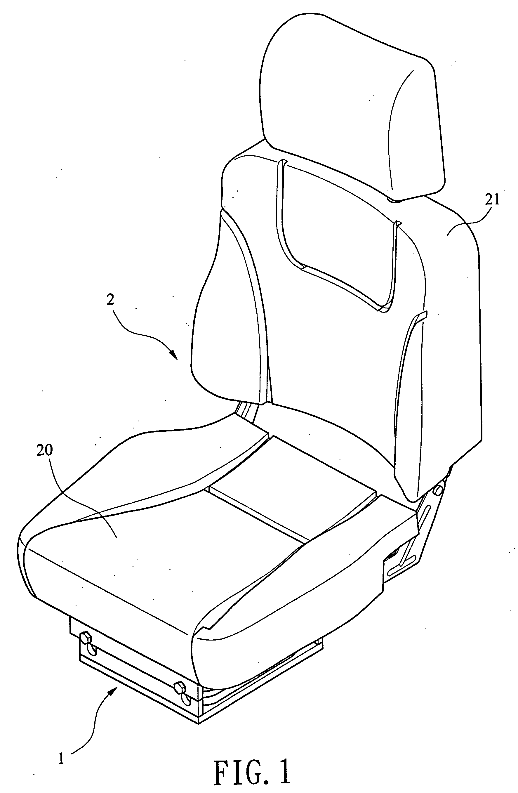
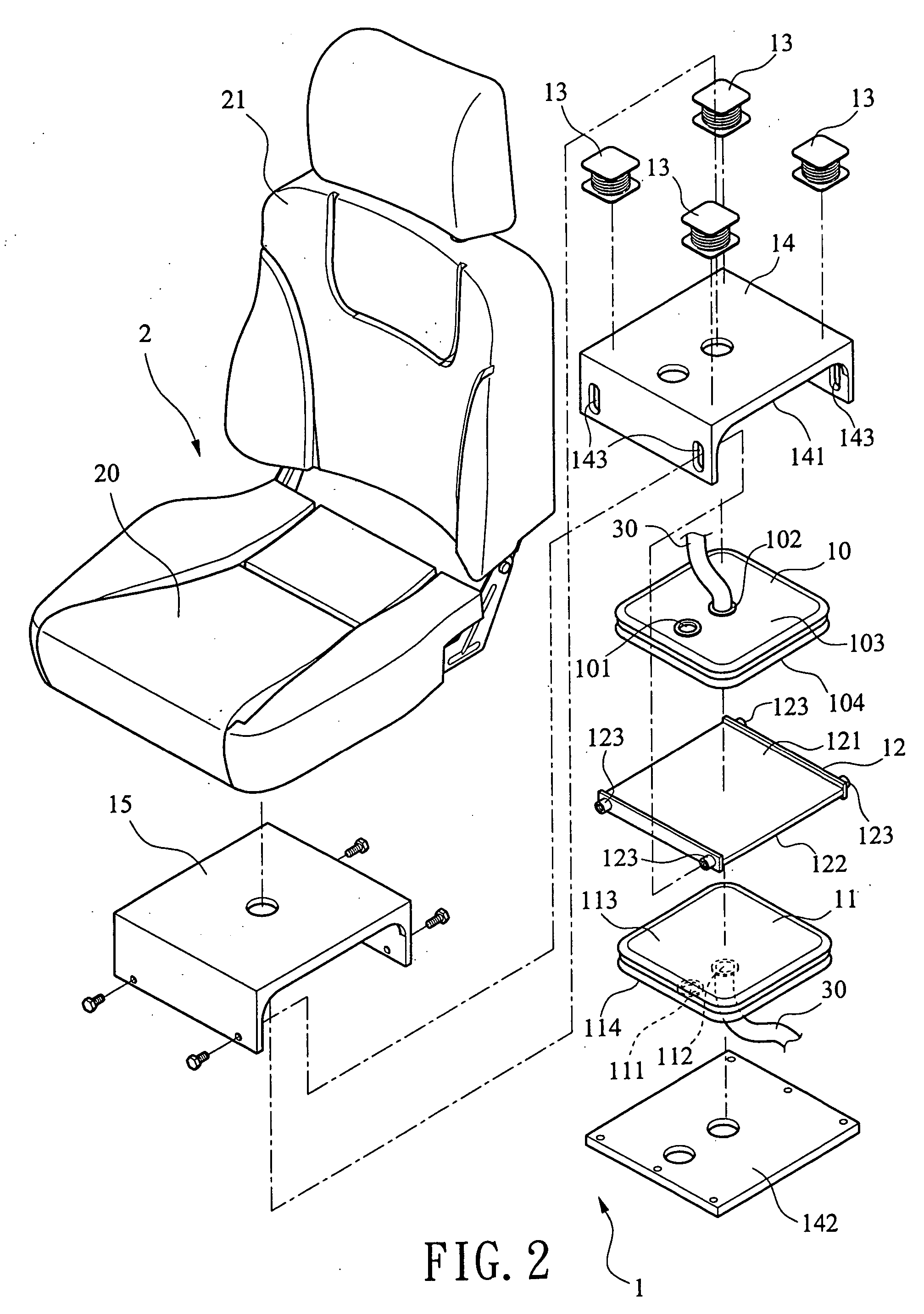
[0012] Refer from FIG. 1 to FIG. 4, an automatic ventilation device for chairs 1 of the present invention is assembled with a cushion 20 of a chair 2. The present invention consists of an upper stretchable air bag 10, a lower stretchable air bag 11. a moveable plate 12 moving upwards and downwards arranged between the two air bags 10, 11, and a plurality of reset spring 13 that returns the moveable plate 12 to original position. The moveable plate 12 is connected with and arranged under the cushion 20 of the chair 2 to form a couple, moving together. There is no limitation in the way of connection while the moveable plate 12 and the cushion 20 move upwards and downwards synchronously under a certain range of height. The upper and lower stretchable air bags 10, 11 are extended or compressed vertically and are disposed on upper side and lower side of the removable plate 12. When the removable plate 12 moves upwards and downwards, one of the upper and the lower air bags 10, 11 is exten...


PUM


Abstract

An automatic ventilation device for chairs uses a moveable plate that moves upwards and downwards along with a cushion, arranged under the cushion. A reset spring for returning is disposed on the removable plate. The upper side and lower side of the removable plate having a stretchable air bag respectively. When the removable plate moves upwards and downwards, one air bag is extended while the other is compressed, working in opposite way. The. upper and lower air bags have one-way air inlets and outlets respectively while the air outlets are connected to the chair cushion and the chair back. Therefore, when the cushion moves due to the movement of users or driving over broken country, the moveable plate moves upwards and downwards synchronously so as to compress one of the upper or lower air bags for blowing air to the chair cushion and chair back continuously. Thus under the condition of energy saving-without a power unit, the device has a cooling effect and makes users comfortable.

Description


Claims


Application Information

Patent Timeline
Owner LEE HWANG PAO
Why Eureka
Try Eureka