Rear projector
a projector and rear projection technology, applied in the field of rear projection devices, can solve the problems of image flickering, image degradation of display images, and temperature increase of light source units, and achieve the effect of good efficiency
- Summary
- Abstract
- Description
- Claims
- Application Information
AI Technical Summary
Benefits of technology
Problems solved by technology
Method used
Image
Examples
first embodiment
1. First Embodiment
[0040] In the below, a rear projector according to a first embodiment of the present invention is described by referring to the accompanying drawings.
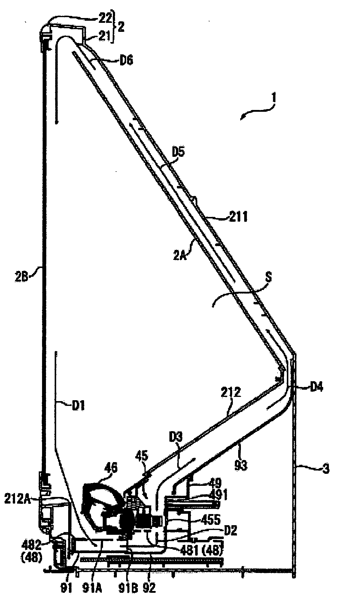
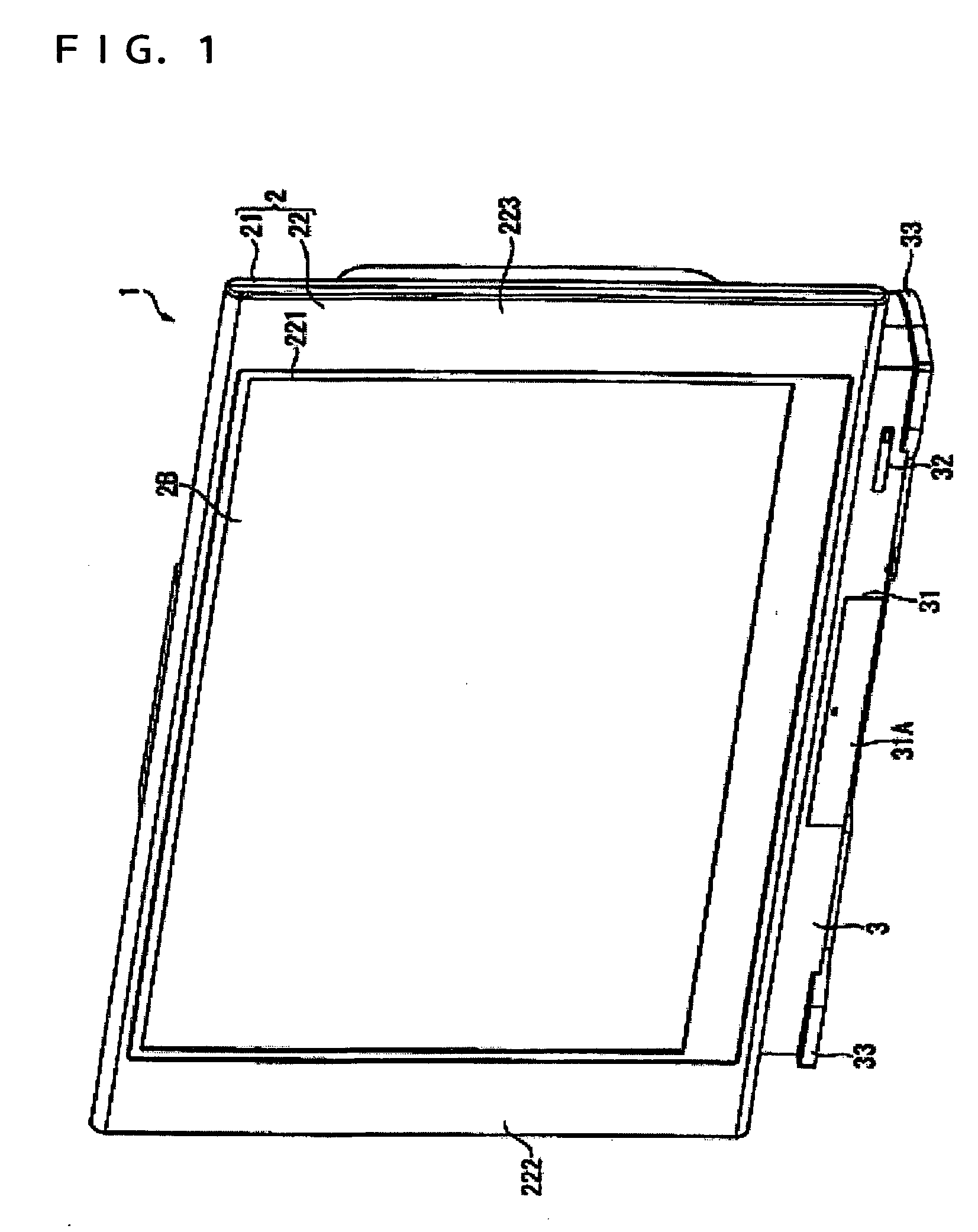
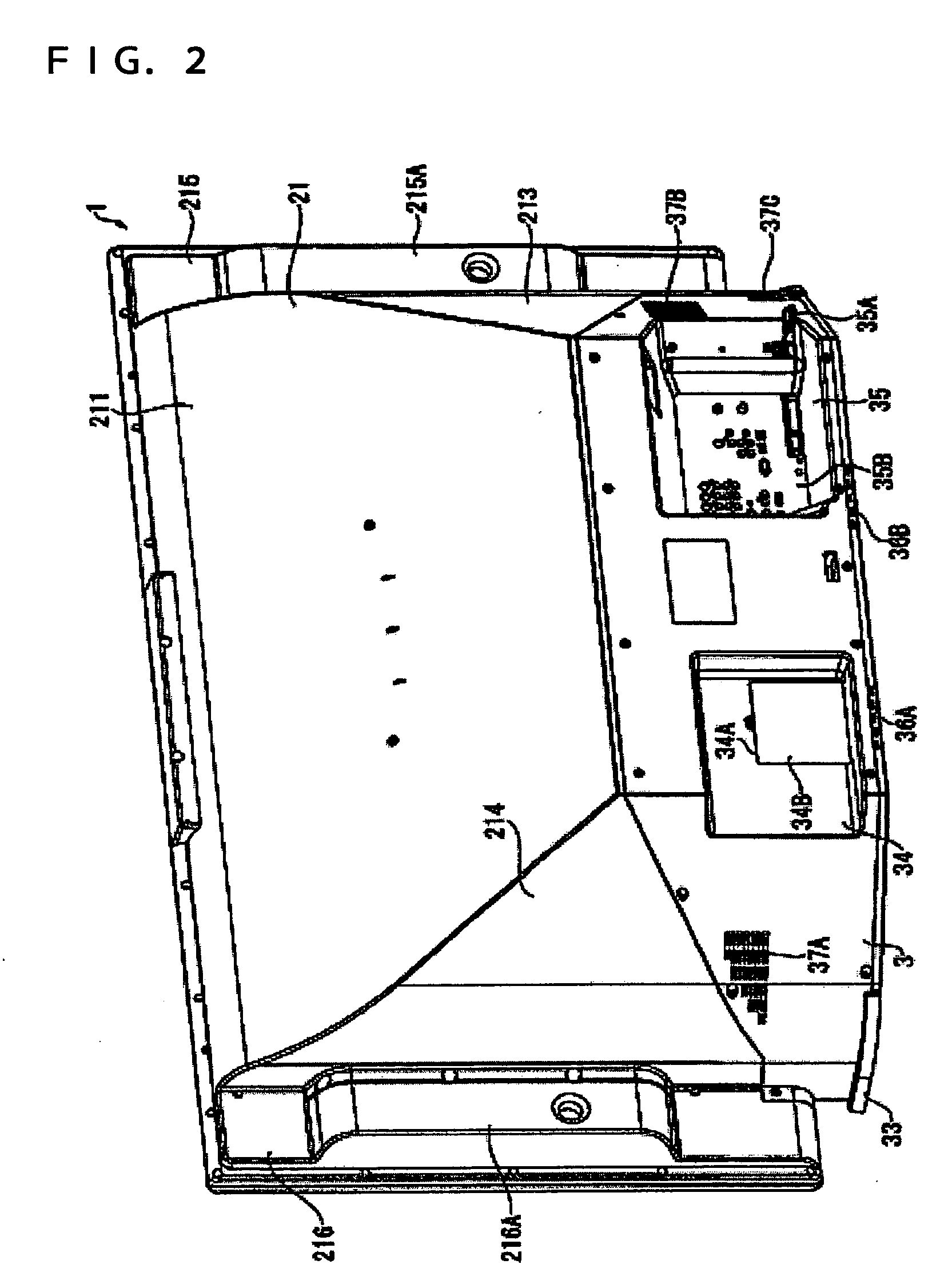
[0041]FIG. 1 is a perspective view of a rear projector 1 of the present embodiment viewed from the front. FIG. 2 is a diagram of the rear projector 1 viewed from the rear, and FIG. 3 is a diagram of the rear projector 1 viewed from the left side. Herein, the left side of FIG. 3 means the left when the rear projector 1 is viewed from the front.
[0042] The rear projector 1 modulates luminous fluxes coming from a light source based on any incoming image information so that optical images are formed. The resulting optical images are enlarged and projected on a light-transmissive screen 2B provided to the rear projector 1.
a. Outer Configuration
[0043] As shown in FIGS. 1 to 3, the rear projector 1 is substantially rectangular in shape viewed from the front, and is configured to include an upper cabinet 2 and a lower ca...
second embodiment
2. Second Embodiment
[0147] Described next is a rear projector 1A according to a second embodiment of the present invention.
[0148] The rear projector 1A of the second embodiment is similar in configuration to the rear projector 1 of the above first embodiment, except that the sealed space S is formed therein with a cooling path for the polarizing beam splitter 423 configuring the optical unit 4. In the below, any components similar or substantially similar to those already described above are provided with the same reference numerals and not described again.
[0149]FIG. 10 is a vertical cross sectional overview of the rear projector 1A having the cross section at the position corresponding to the polarizing beam splitter 423. FIG. 11 is a schematic view of a cooling path of the polarizing beam splitter 423.
[0150] In the rear projector 1A of the present embodiment, a path E is formed in the sealed space S for the air cooling the polarizing beam splitter 423. As shown in FIGS. 10 and ...
third embodiment
3. Third Embodiment
[0169] Described next is a rear projector according to a third embodiment of the invention.
[0170] The rear projector of the third embodiment is similar in configuration to the rear projector 1 of the above first embodiment, except that the cooling fan 91 directing the air to the electro-optical device45 directs the air also to the polarizing beam splitter 423.
[0171]FIG. 12 is a plane overview schematically showing the electro-optical device 45 of the rear projector of the third embodiment, and a duct 97 that guides the cooled air to the polarizing beam splitter 423. FIG. 13 is a diagram schematically showing the cooling path for cooling the electro-optical device 45 and the polarizing beam splitter 423.
[0172] As shown in FIGS. 12 and 13, similarly to the rear projector 1 of the first embodiment, the rear projector of the present embodiment is provided with the cooling fan 91, and ducts 97 and 98, all of which are placed below the projection lens 46 (not shown i...
PUM
| Property | Measurement | Unit |
|---|---|---|
| luminous fluxes | aaaaa | aaaaa |
| temperature | aaaaa | aaaaa |
| size | aaaaa | aaaaa |
Abstract
Description
Claims
Application Information
 - R&D
- Intellectual Property
- Life Sciences
- Materials
- Tech Scout
- Unparalleled Data Quality
- Higher Quality Content
- 60% Fewer Hallucinations
Browse by: Latest US Patents, China's latest patents, Technical Efficacy Thesaurus, Application Domain, Technology Topic, Popular Technical Reports.
© 2025 PatSnap. All rights reserved.Legal|Privacy policy|Modern Slavery Act Transparency Statement|Sitemap|About US| Contact US: help@patsnap.com


