Camera system equipped with camera shake correction function

a technology of camera system and function, applied in the field of camera system, can solve the problems not eliminating the problem of camera shake correction function not functioning, and not eliminating the problem of complex communication between photo lenses and camera bodies

Inactive Publication Date: 2007-01-04
OLYMPUS IMAGING CORP
View PDF7 Cites 23 Cited by
  • Summary
  • Abstract
  • Description
  • Claims
  • Application Information

AI Technical Summary

Benefits of technology

[0009] According to the present invention, in the lens changeable camera system in which a photography lens and a camera body are connected detachably with each other, the camera system comprises a transmission circuit comprised by the camera body and which is a circuit for transmitting control information used for controlling the photography lens from the camera body thereto; a reception circuit comprised by the photography lens and which is a circuit for receiving the control information tran...

Problems solved by technology

There have been problems associated with a diversification of functions of a photo lens and a camera body as described above, such as complex communication between a photo lens and the camera body.
The method noted in the Laid-Open Japanese Patent Application Publication No. 08-114825, however, has not eliminated the problems of the cam...

Method used


Image

  • Camera system equipped with camera shake correction function
  • Camera system equipped with camera shake correction function
  • Camera system equipped with camera shake correction function

Examples


first embodiment

(1) First Embodiment

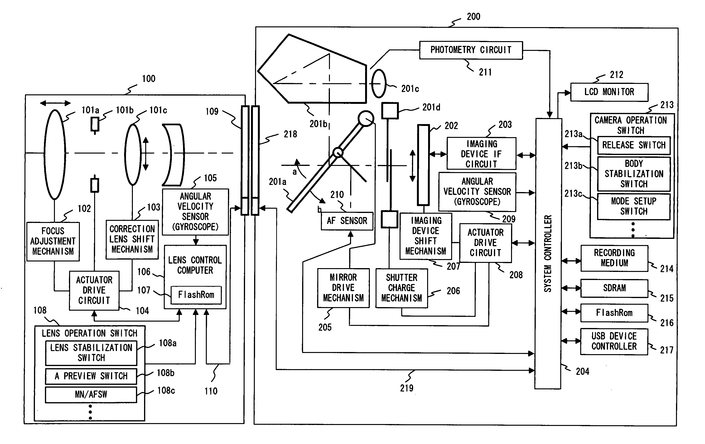
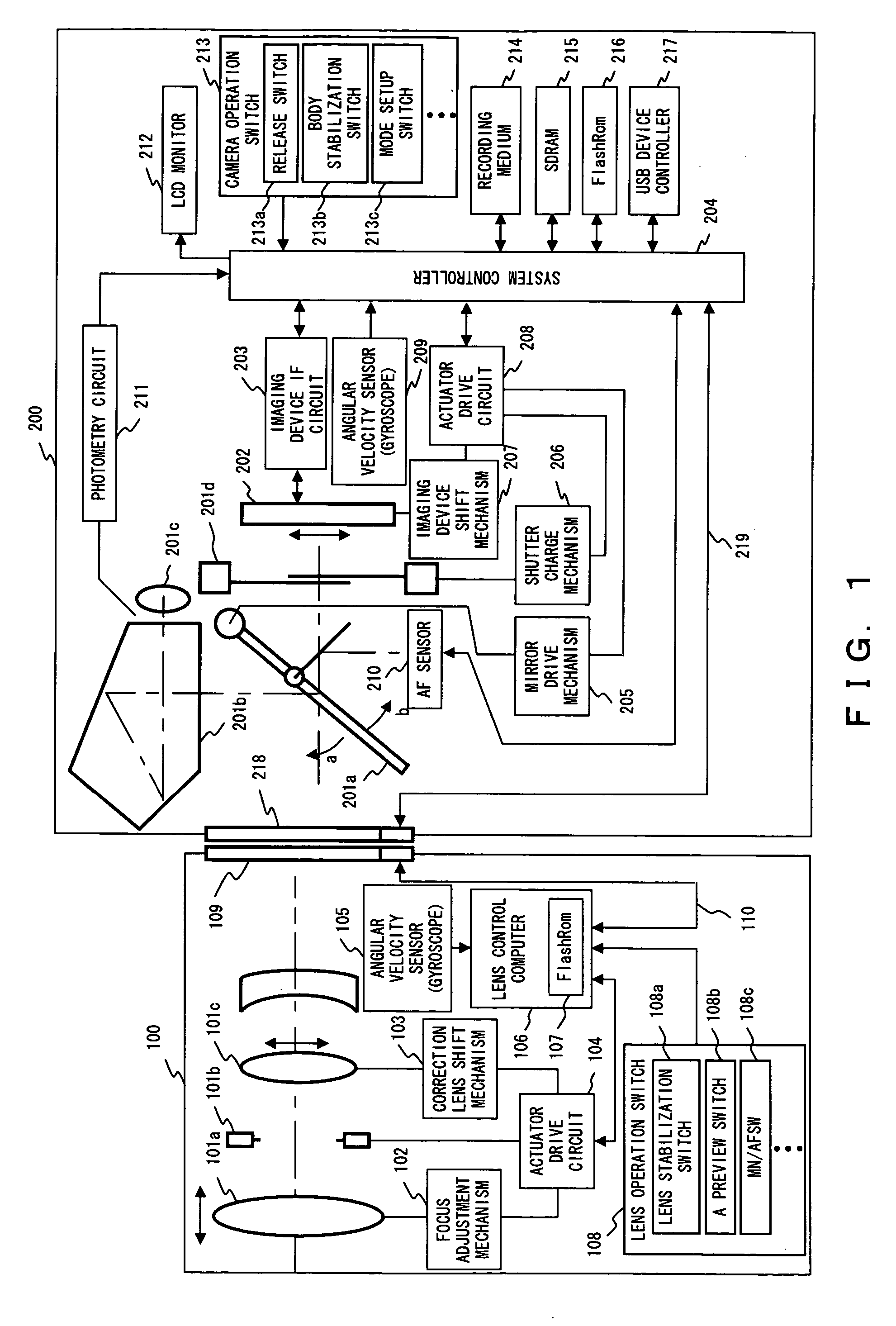
[0041]FIG. 1 is a diagram showing an overall configuration of a camera system according to the first embodiment.

[0042] A camera system shown by FIG. 1 comprises a photography lens (“photo lens” hereinafter) 100 and a camera body 200 which are mutually detachably connected with each other.

[0043] The photo lens 100 comprises an optical system which includes at least a focus lens 101a for adjusting focus, a diaphragm 101b for limiting an incident light amount and a correction lens 101c for changing an optical axis of the incident light.

[0044] Also, photo lens 100 comprises a focus adjustment mechanism 102 for performing a focus adjustment by moving the focus lens 101a in the optical axis direction, a correction lens shift mechanism 103 for shifting the correction lens 101c on a plane perpendicular to the optical axis or tilting the correction lens 101c, an actuator drive circuit 104 for driving the diaphragm 101b, focus adjustment mechanism 102 and correction len...

second embodiment

(2) Second Embodiment

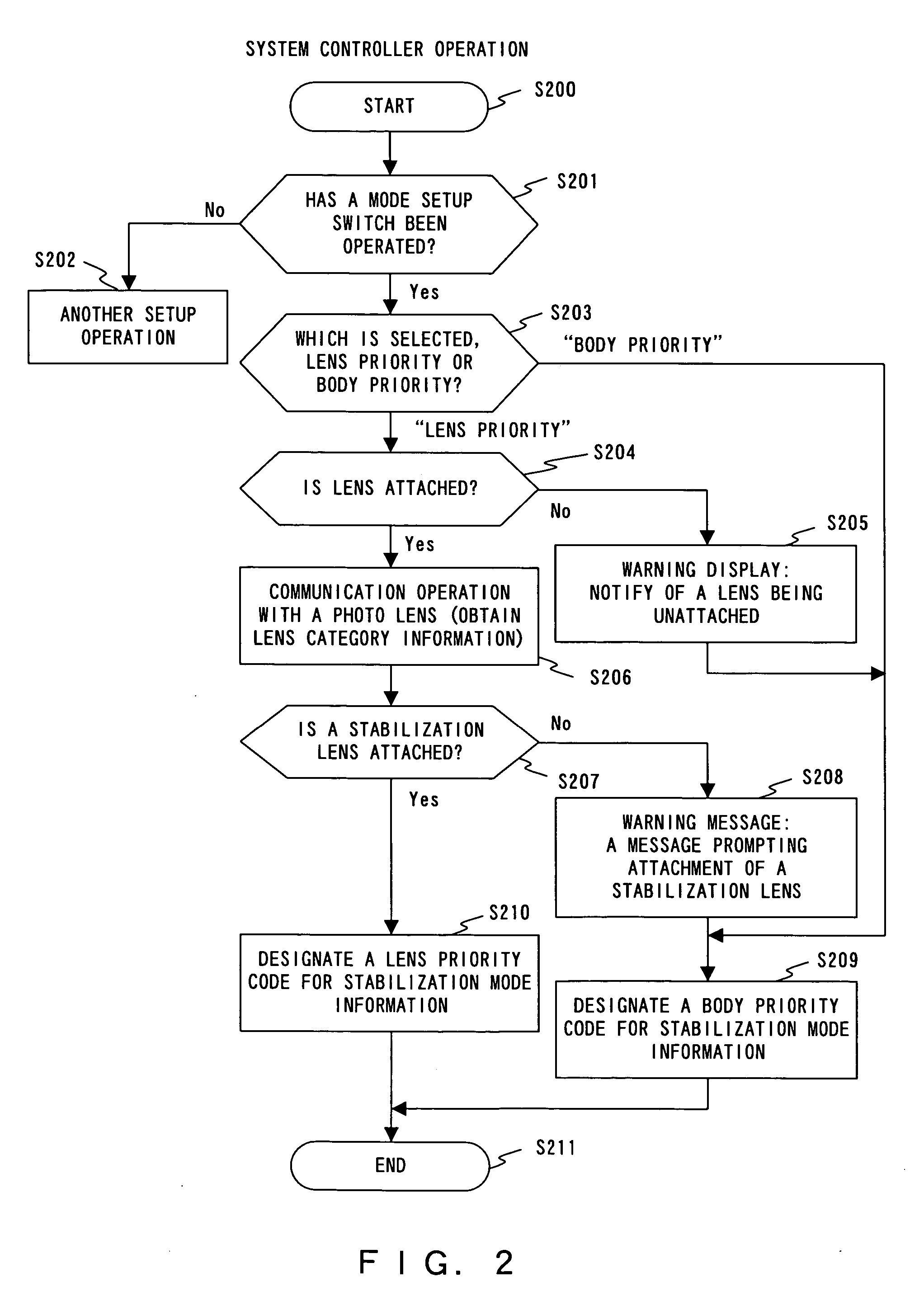
[0200]FIGS. 18A through 18C show a flow chart showing a photography operation of a camera system according to a second embodiment. The following describes a stabilization operation of the camera system according to the second embodiment based on the flow chart.

[0201] As a camera operation switch 213 is operated, an interrupt signal is input to a system controller 204, for instance, and an MPU comprised thereby executes a program stored in a predefined address within a Flash Rom 216 in response to the interrupt signal, thereby a photographing operation, et cetera, being started (S1800).

[0202] Note that while the process described in the following is implemented by the MPUs respectively comprised by a lens control computer 106 and a system controller 204 executing instructions described in a prescribed program, the description of the present specification handles the lens control computer 106 and system controller 204 as the subjects of the respective processes ...

third embodiment

(3) Third Embodiment

[0246]FIG. 20 is a diagram showing an overall configuration of a camera system according to the third embodiment.

[0247] The camera system shown by FIG. 20 is constituted by a photo lens 100 and a camera body 500 which are mutually detachably connected to each other.

[0248] The photo lens 100 is one described in association with FIG. 1. The camera body 500 is one further comprising a control panel 501 for displaying various pieces of photography information and a finder display unit 502 for displaying photography information within a finder, in addition to the camera body 200 described in association with FIG. 1.

[0249] The control panel 501 displays not only displays relating to the stabilization functions (simply “stabilization display 506” hereinafter) of the photo lens 100 and camera body 500, but also photometry mode, AF mode, image quality mode, shutter speed, aperture value of a diaphragm, remaining battery power, the number of available imaging frames, co...


PUM


Abstract

A camera system according to the present invention comprises: a transmission circuit comprised by the camera body and which is a circuit for transmitting control information used for controlling the photography lens; a reception circuit comprised by the camera body and which is a circuit for receiving the control information; a camera shake correction unit comprised by the camera body and which is the unit for compensating a shake generated in a image on a photographed surface; and a camera shake correction control unit for changing an operation condition of the camera shake correction unit when the reception circuit receives prescribed control information for issuing a setup instruction for a photographing preparation in order to provide the camera system enabling a control of a stabilization function comprised by a photography lens without complicating a communication between the photography lens and a camera body.

Description

CROSS-REFERENCE TO RELATED APPLICATIONS [0001] This application claims benefit of Japanese Patent Application No. 2005-194072 filed on Jul. 1, 2005, the contents of which are incorporated by this reference. BACKGROUND OF THE INVENTION [0002] 1. Field of the Invention [0003] The present invention relates to a camera system enabling a detachable attachment of a photography lens with a camera body, and in particular to a camera system enabling an operation of a camera shake correction by using apart or the entirety of a camera shake correction function which is equipped on the photography lens or the camera body. [0004] 2. Description of the Related Art [0005] In recent years, many of camera systems equipped with a camera shake correction function have been proposed for the purpose of improving operability. For a camera system allowing a detachable attachment of a photography lens (sometimes “photo lens” hereinafter) with a camera body, a camera system equipped with a camera shake corr...

Claims


Application Information

Patent Timeline
IPC IPC(8): G03B17/00
CPCG03B5/02G03B17/02G03B2217/005H04N5/23209G03B2205/0038H04N5/23258H04N5/23287G03B2205/0015H04N5/23248H04N23/663H04N23/68H04N23/6812H04N23/687
Inventor SHIRATORI, KAZUTOSHI
Owner OLYMPUS IMAGING CORP
Why Eureka
Try Eureka