Mechanical adapter assembly

a technology of mechanical adapters and components, applied in the direction of gearing, gear connection, gearing details, etc., can solve the problem of small amount of oil permanently on the bottom, and achieve the effect of better ventilation

Active Publication Date: 2007-01-04
VOLVO LASTVAGNAR AB
View PDF11 Cites 5 Cited by
  • Summary
  • Abstract
  • Description
  • Claims
  • Application Information

AI Technical Summary

Benefits of technology

[0024] According to another embodiment, the front plate may comprise openings making it possible to evacuate oil and cool it in an independent heat exchanger. In this case, a certain number of hoses are used to connect the openings located on the front plate to the independent heat exchanger. This configuration makes it possible, in particular, to locate the heat exchanger in an area that is better ventilated or less exposed to soiling.
[0025] In practice, the front plate may be obtained by using a coreless moulding process. In this way, it is possible to clean every area of the part, making sure that not a single grain of sand is left behind.
[0026] In this case, a cover may be separately mounted on the front plate in order to ensure that oil is distributed to those areas that require extra oil for satisfactory lubrication. Thus, the front plate comprises an opening making it possible to provide maintenance access to the mechanical adapter assembly, this opening being closed by a cover.
[0027] Advantageously, the distinctive pipe section may comprise at least one opening making it possible to precisely lubricate a given area of the mechanical adapter assembly.

Problems solved by technology

In fact, when the rotation speed of the various components inside the mechanical adapter assembly is high, these components then constantly agitate the oil and, consequently, only a small quantity of oil remains permanently on the bottom of the mechanical adapter assembly.

Method used


Image

  • Mechanical adapter assembly
  • Mechanical adapter assembly
  • Mechanical adapter assembly

Examples


Embodiment Construction

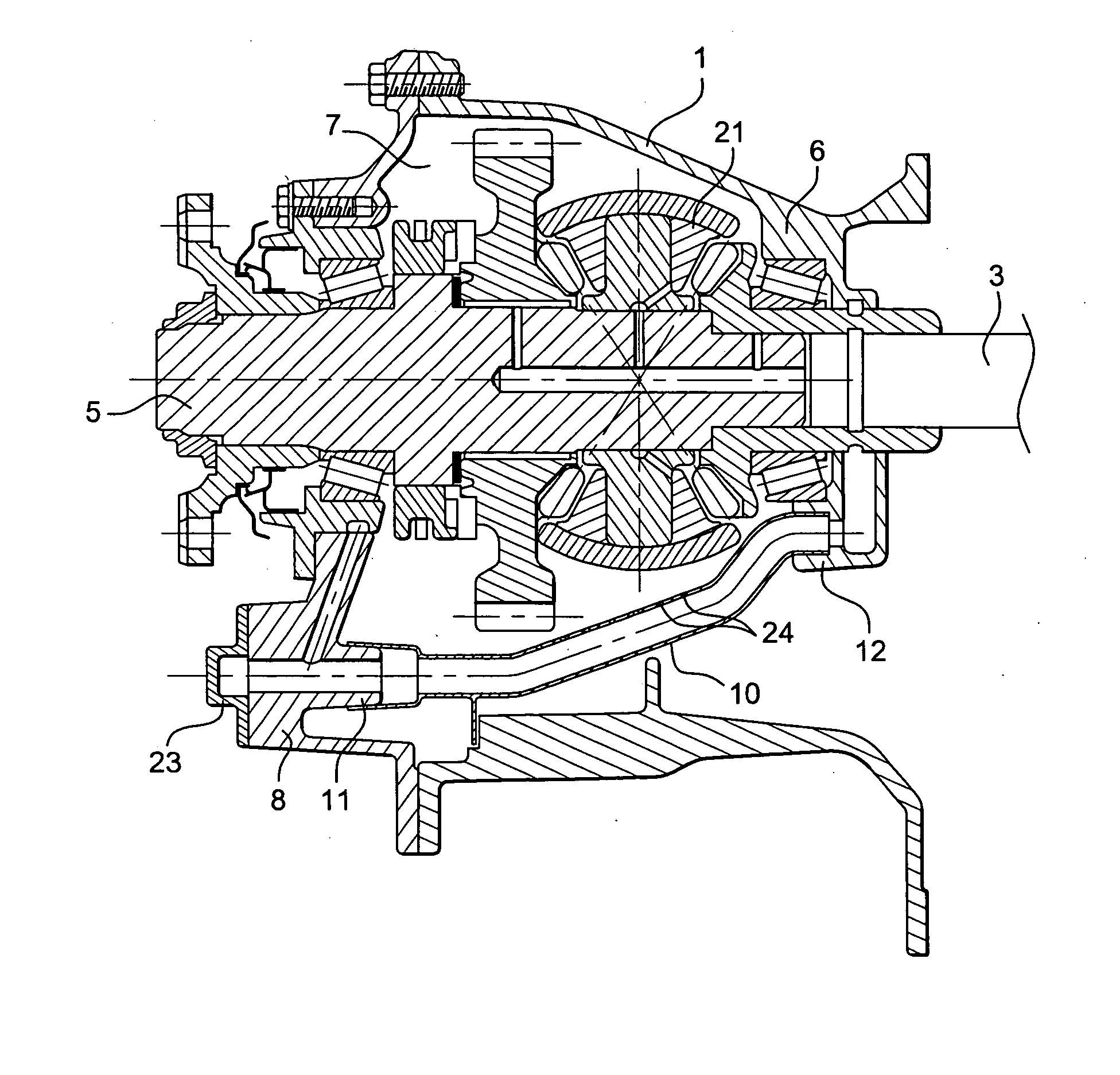
[0037] As stated earlier, the invention relates to a mechanical adapter assembly of a transmission line for a motor vehicle comprising shafts rotatably guided by various bearings and couplings for driving the various shafts.

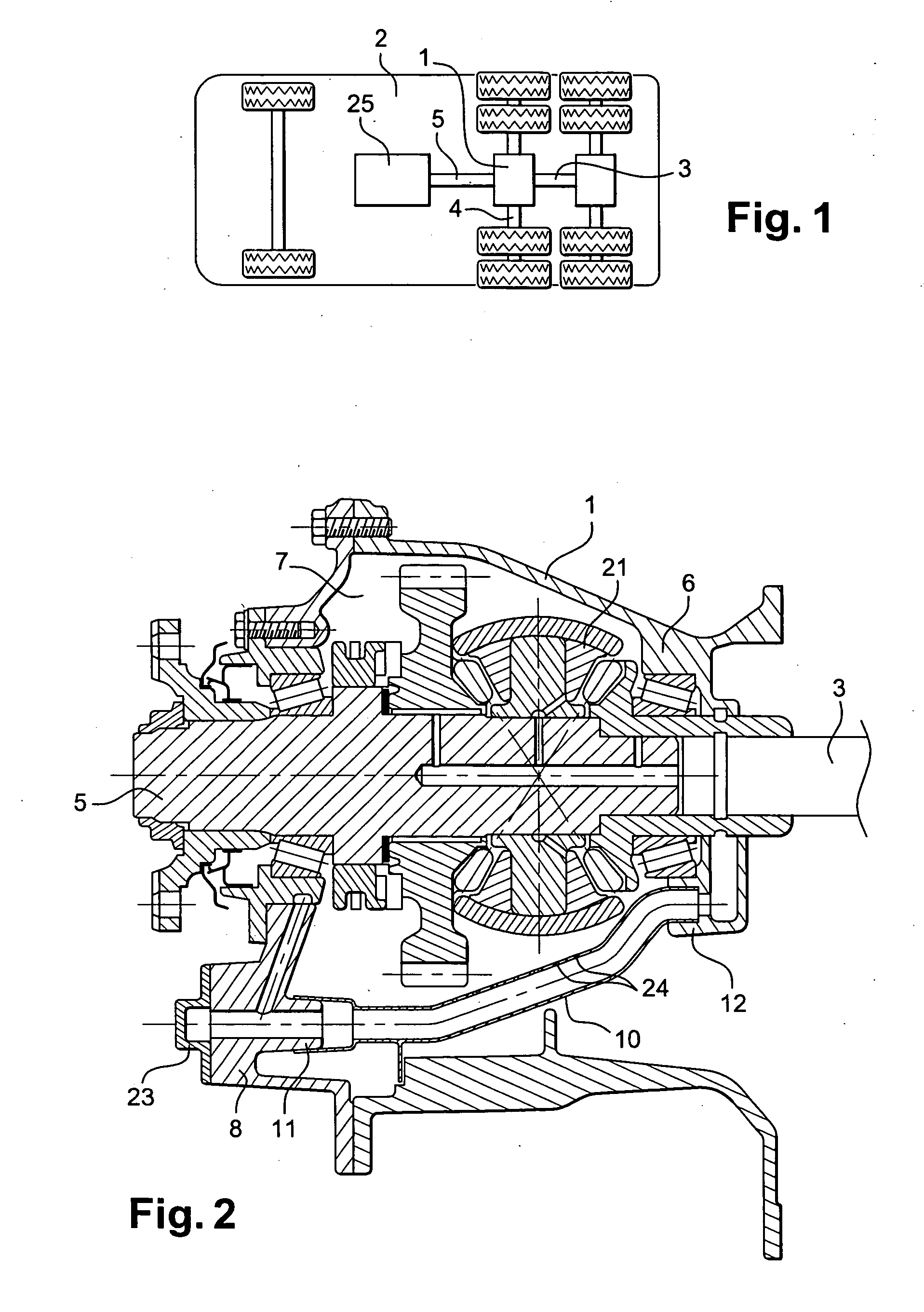
[0038] As shown in FIG. 1, a motor vehicle (2) comprises an engine assembly (25) that drives a shaft (5). This shaft (5) enters the mechanical adapter assembly (1) and drives, in particular, output shaft (3) linked to the rear axle. Depending on the load and / or road conditions, it may or may not be necessary to drive shafts (3) and (5) synchronously and, consequently, to transmit the same engine torque to both axles.

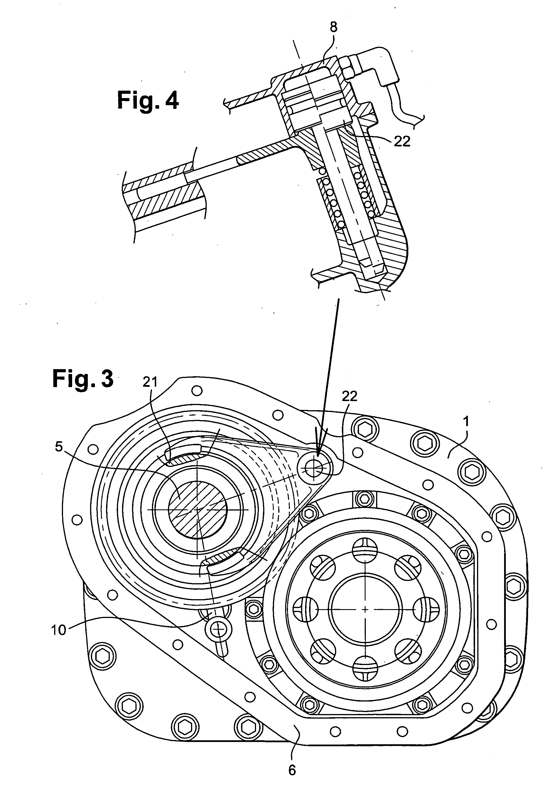
[0039] As shown in FIG. 2, shafts (3) and (5) are linked together by means of an inter-axle differential (21). According to the invention, the mechanical adapter assembly comprises a differential carrier (6) acting as a crankcase and comprising a front aperture (7). This aperture (7) is closed by means of a front plate (8) which integrates, in parti...


PUM


Abstract

The invention relates to the mechanical adapter assembly (1) of the transmission line for a motor vehicle (2) comprising shafts (3, 4, 5) rotatably guided by different bearings and couplings for driving said different shafts (3, 4, 5). Said inventive assembly is characterised in that it also comprises a differential carrier (6) which is used in the form of a crankcase containing the oil for lubricating the different bearings and couplings and provided with a front aperture (7), a front plate (8) integrating a pump (9) and making it possible to close said front aperture (7) of the differential support (6) and an attached pipe section (10) which supplies the oil from said front plate (7) to the differential support (6) and interacts with additional fixtures (11, 12) to the front plate (8) and the differential carrier (6).

Description

FIELD OF THE INVENTION [0001] The invention relates to a transmission component for a motor vehicle, especially a vehicle comprising several powered axles such as a lorry or a construction site vehicle. The transmission line of such vehicles comprises a mechanical adapter assembly making it possible to rotatably guide several transmission shafts and also to distribute the engine torque to the axles and the wheels. [0002] The invention refers more especially to a mechanical adapter assembly the main housing of which is obtained through a coreless moulding process so as to allow so-called “natural” removal from the mould. DESCRIPTION OF THE PRIOR ART [0003] Generally speaking, the mechanical adapter assemblies fitted in the transmission line of a motor vehicle comprise a main crankcase, also referred to as a differential carrier, which is obtained through a sand moulding process and requires the use of several cores in order to achieve the complex shapes that are sought after. [0004] ...

Claims


Application Information

Patent Timeline
Patent Type & Authority Applications(United States)
IPC IPC(8): H01R13/625B60K17/36F16H57/023F16H57/033F16H57/04
CPCF16H57/033F16H57/0404F16H2057/0235F16H57/0441F16H57/0483F16H57/043
Inventor IMBERT, FREDERI
Owner VOLVO LASTVAGNAR AB
Why Eureka
Try Eureka