Luggage scale

a technology for luggage scales and weights, applied in the direction of measuring devices, instruments, weighing devices, etc., can solve the problems of physical complexity and relatively high application cost of the majority of parts

Inactive Publication Date: 2007-01-11
GILL MICHAEL R
View PDF8 Cites 46 Cited by
  • Summary
  • Abstract
  • Description
  • Claims
  • Application Information

AI Technical Summary

Problems solved by technology

These for the most part are physically complicated...

Method used


Image

  • Luggage scale
  • Luggage scale
  • Luggage scale

Examples


second embodiment

[0042] the present invention uses the internal suitcase frame as the base plate as shown in FIGS. 3 and 4. Here base plate 1 of FIGS. 1 and 2 is replaced by the frame 13 of the suitcase.

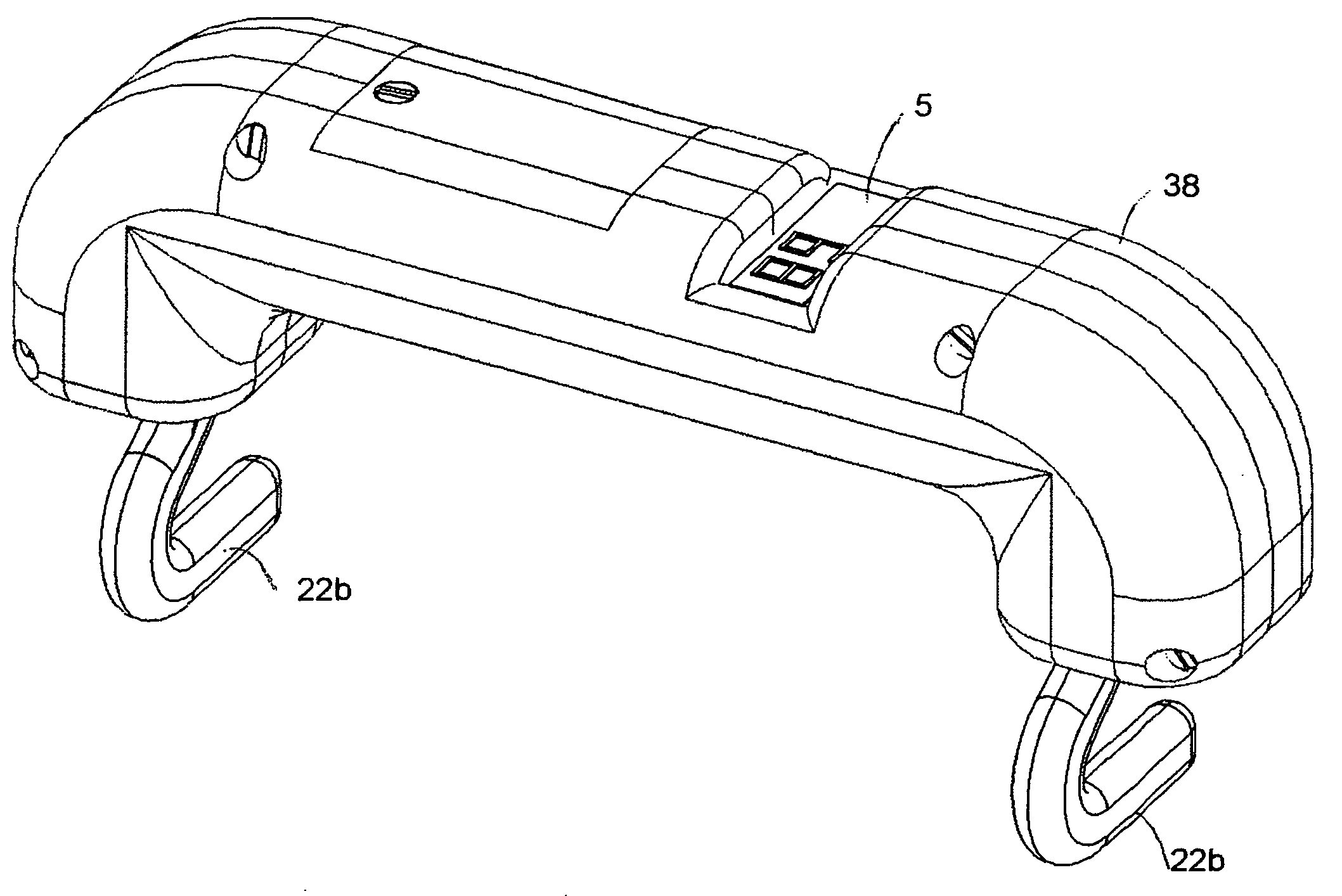
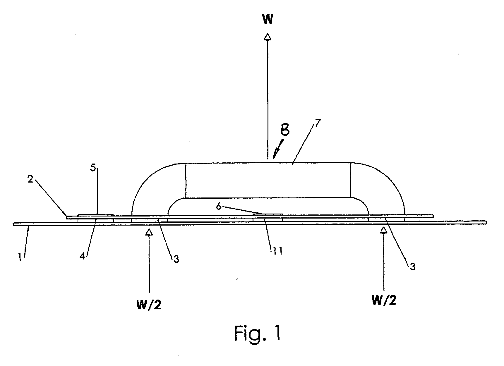
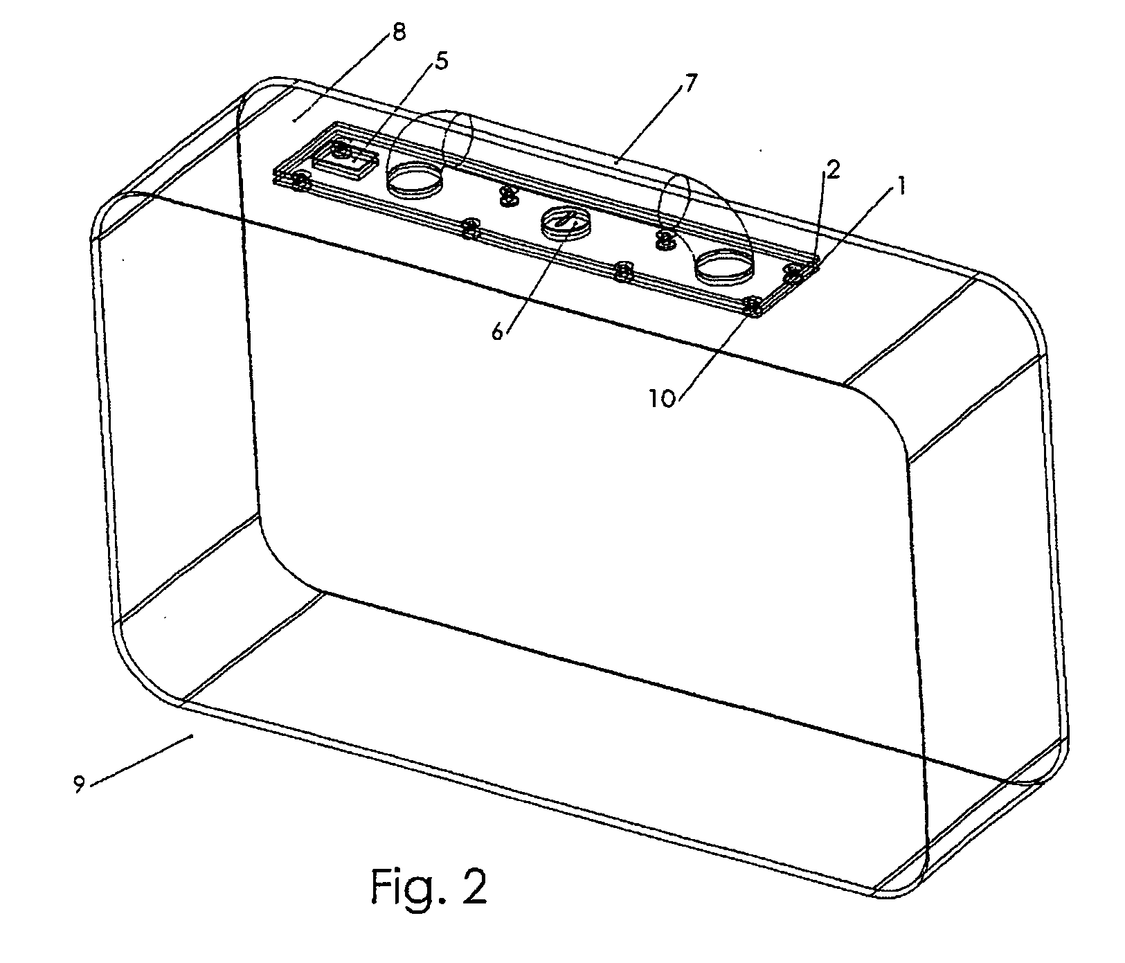
[0043] A third embodiment of the present invention incorporates all of the electronics and sensors into the luggage handle as shown in FIG. 5 for ease of retrofit to a piece of luggage. The display 5 is embedded and offset towards one end of the handle for ease of viewing. The battery compartment 6 is located in a convenient location but not necessarily as shown. The load measuring sensors 3 are mounted inline with the downwardly disposed ends of handle 7 so as to be sandwiched between handle 7 and handle mounts 12 so that sensors can measure the full load W of the suitcase when handle 7 is lifted. Thus as seen in FIG. 6, the third embodiment of the present invention is shown with its integrated handle attached to suitcase 9 by the mounting of handle mounts 12 to suitcase frame 13.

fourth embodiment

[0044] In a fourth embodiment, handle 14 is retractable. Handle 14 slides up and down for example by the upwardly extending ends of carrier 15 telescopically sliding within the corresponding downwardly disposed ends of handle 14. Alternatively, as seen in FIGS. 7 and 8, handle 14 and carrier 15 form a single unitary rectangular piece and the upwardly extending ends of carrier 15 are free to slide up and down in corresponding apertures in the suitcase frame, or base plate 1 or the like. In either case, lifting of handle 14 eventually causes carrier 15 to compress the load sensors 16 as shown in FIG. 8. The load sensors and electronics 16 convert the sensor signal to be displayed on the weight display 5. When the suitcase is lifted by the handle 14, the carrier part of the handle 15 engages and compresses the load sensors and electronics 16 with the weight of the luggage. The sensor signals are converted and displayed on display 5 while the luggage is supported by the handle and for s...


PUM


Abstract

A luggage weight measuring device for integration into a luggage case, or between the luggage case and handle or for mounting to the luggage case handle. In one embodiment at least one electronic load measuring sensor is mounted directly between the handle and the luggage case, for example to a deformable member which deforms as the handle is lifted to take up the load carried by the luggage case. Deformation is mathematically related to the load. A processor determines the load corresponding to the deformation as detected by the sensors and displays the load on a user viewable display on the luggage case or handle.

Description

CROSS REFERENCE TO RELATED APPLICATION [0001] This application claims priority from U.S. Provisional Patent Application No. 60 / 595,440 filed Jul. 5, 2005 entitled Luggage Scale.FIELD OF THE INVENTION [0002] This invention relates to luggage weight measuring devices that are either integrated into the luggage, the luggage handle or attached to the luggage handle. The present invention incorporates electronic load measuring sensors directly between the handle and the luggage that the handle is attached to. BACKGROUND OF THE INVENTION [0003] It is known that mechanical means exist to measure luggage weight by integrating typically spring loaded mechanisms into the luggage handle, or the luggage itself at the point of connection with the handle. These for the most part are physically complicated and therefore relatively expensive for the application. [0004] Applicant is aware of patents regarding such as U.S. Pat. No. 2,518,973 issued to Atherton on Aug. 15, 1950 titled “Weighing Device...

Claims


Application Information

Patent Timeline
IPC IPC(8): G01G19/56
CPCG01G19/58
Inventor GILL, MICHAEL
Owner GILL MICHAEL R
Why Eureka
Try Eureka