Adaptive synchronous rectifier control

a synchronous rectifier and control technology, applied in the direction of pulse technique, dc-dc conversion, power conversion systems, etc., can solve the problems of variation of the operational performance of synchronous, significant loss of the diode dsub>1 /sub>operating as the output rectifier, and inability to reliably detect conventional synchronous rectifier controllers

Inactive Publication Date: 2015-05-07
DIALOG SEMICONDUCTOR INC
View PDF6 Cites 23 Cited by
  • Summary
  • Abstract
  • Description
  • Claims
  • Application Information

AI Technical Summary

Problems solved by technology

In high output current applications, the conduction loss of the diode D1 operating as the output rectifier is significant.
However, conventional synchronous rectifier controllers cannot reliably detect the optimum point at which to place the synchronous rectifier MOSFET from the on state to the off state.
This results in variation of operational performance of synchronous rectification systems including increased power loss due to excessive body diode conduction or reverse current to occur.

Method used


Image

  • Adaptive synchronous rectifier control
  • Adaptive synchronous rectifier control
  • Adaptive synchronous rectifier control

Examples


Embodiment Construction

[0017]The Figures (FIG.) and the following description relate to various embodiments by way of illustration only. It should be noted that from the following discussion, alternative embodiments of the structures and methods disclosed herein will be readily recognized as viable alternatives that may be employed without departing from the principles discussed herein.

[0018]Reference will now be made in detail to several embodiments, examples of which are illustrated in the accompanying figures. It is noted that wherever practicable similar or like reference numbers may be used in the figures and may indicate similar or like functionality. The figures depict various embodiments for purposes of illustration only. One skilled in the art will readily recognize from the following description that alternative embodiments of the structures and methods illustrated herein may be employed without departing from the principles described herein.

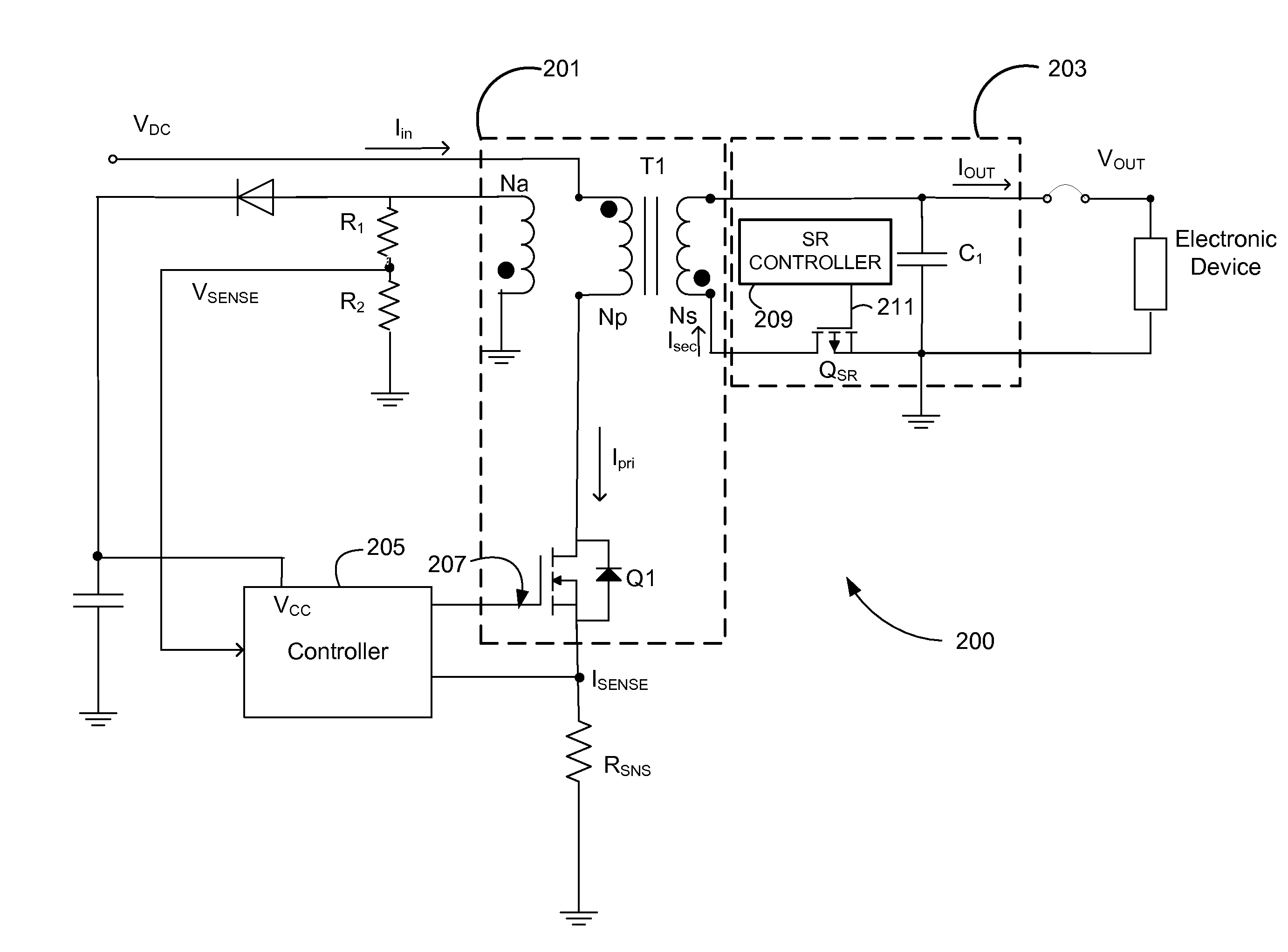
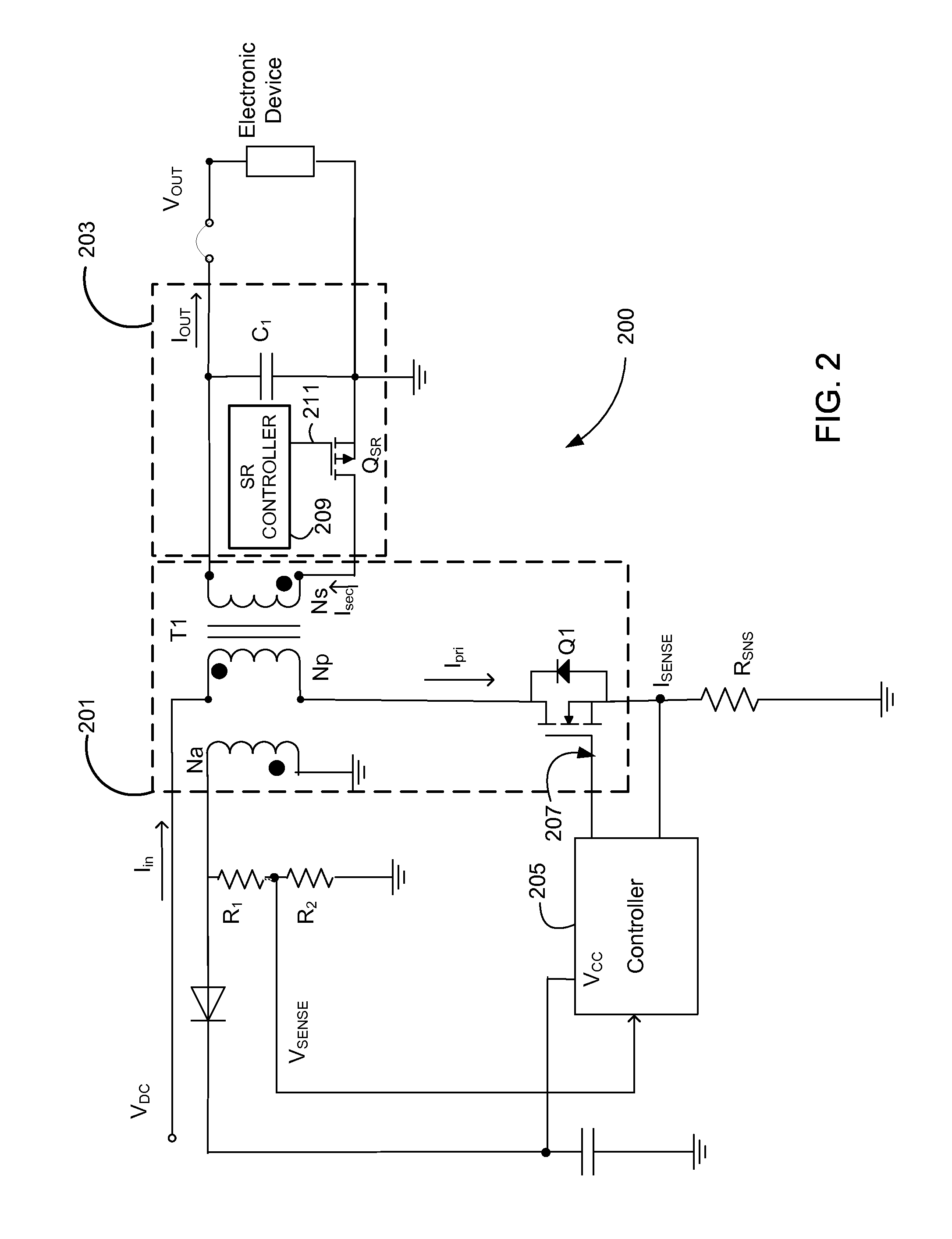
[0019]FIG. 2 is a circuit diagram of a flyback type sw...


PUM


Abstract

The embodiments herein describe a switched mode power converter. In particular, the embodiments herein disclose techniques for adaptive synchronous rectification control. The switched mode power supply includes a synchronous rectifier controller that determines when to turn off the synchronous rectifier during each switching cycle based on a reference signal corresponding to when substantially all the power stored in a transformer of the power supply has been delivered to an electronic load. The synchronous rectifier controller may determine whether to adjust the reference signal used by the synchronous rectifier controller to turn off the synchronous rectifier during subsequent switching cycles.

Description

BACKGROUND[0001]1. Field of Technology[0002]Embodiments disclosed herein relate generally to switching power converters, and more specifically, to techniques for adaptive synchronous rectification control.[0003]2. Description of the Related Arts[0004]FIG. 1 is a circuit diagram of a conventional flyback type switching power converter 100 that uses a switch Q1 such as a metal-oxide-semiconductor field-effect transistor (MOSFET). The switching power converter 100 includes a power stage 101 and a secondary output stage 103. Power stage 101 includes the switch Q1 and a power transformer T1. Power transformer T1 includes primary winding Np, secondary winding Ns, and auxiliary winding Na. Secondary output stage 103 includes diode D1 and output capacitor C1. A controller 105 controls the ON state and the OFF state of switch Q1 using output drive signal 107 in the form of a pulse with on-times (TON) and off-times (TOFF).[0005]AC power is received from an AC power source (not shown) and is r...

Claims


Application Information

Patent Timeline
Patent Type & Authority Applications(United States)
IPC IPC(8): H02M3/335
CPCH02M3/33592H03K2017/307Y02B70/10
Inventor MALININ, ANDREY B.
Owner DIALOG SEMICONDUCTOR INC
Why Eureka
Try Eureka