
Electrochemical machining bipolar electrode of revolution body surface boss structure and electrochemical machining method of electrochemical machining bipolar electrode

A bipolar electrode and boss structure technology, applied in the direction of processing electrodes, electric processing equipment, electrochemical processing equipment, etc., can solve problems such as difficulties, complex implementation of composite magnetic field devices, and complex movement forms

Active Publication Date: 2016-04-27
NANJING UNIV OF AERONAUTICS & ASTRONAUTICS
View PDF9 Cites 23 Cited by
  • Summary
  • Abstract
  • Description
  • Claims
  • Application Information

AI Technical Summary

Problems solved by technology

[0006] In the above-mentioned patents, the compound magnetic field, bipolar electrode, and auxiliary electrode tube all improve the precision of electrolytic machining by changing the electric field distribution in the machining gap and reducing the stray current in the non-processing area, but they all have their limitations, and the compound magnetic field device is relatively complicated. It is difficult to implement, bipolar electrodes and auxiliary electrode tubes are used to solve the problem of stray corrosion on the side walls of holes or pits
Because in the above-mentioned new thin-wall casing electrolytic machining method, the workpiece anode and the tool cathode are relatively rotating, and its motion form is more complicated than traditional electrolytic machining, so it is necessary to design a new type of electrode to improve the boss machining of the workpiece surface Forming precision

Method used


Image

  • Electrochemical machining bipolar electrode of revolution body surface boss structure and electrochemical machining method of electrochemical machining bipolar electrode
  • Electrochemical machining bipolar electrode of revolution body surface boss structure and electrochemical machining method of electrochemical machining bipolar electrode
  • Electrochemical machining bipolar electrode of revolution body surface boss structure and electrochemical machining method of electrochemical machining bipolar electrode

Examples


Embodiment Construction

[0028] combine figure 1 , 2 , 3, 4, 5 illustrate the implementation process of the present invention:

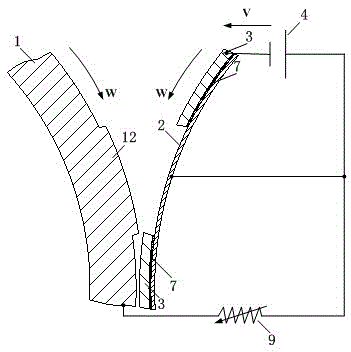
[0029] figure 1 Schematic diagram of the dual-electrode structure for electrolytic machining of low bosses with a height of 0-1mm. The auxiliary electrode is fixed on the inner wall of the tool cathode and is insulated by an insulating layer. The anode of the workpiece is connected in series with the electronic load and then connected to the positive pole of the power supply in parallel with the auxiliary electrode, and the cathode of the tool is connected to the negative pole of the power supply. The electronic load is set to a constant voltage mode during operation to ensure a stable positive potential difference between the auxiliary electrode and the anode of the workpiece.

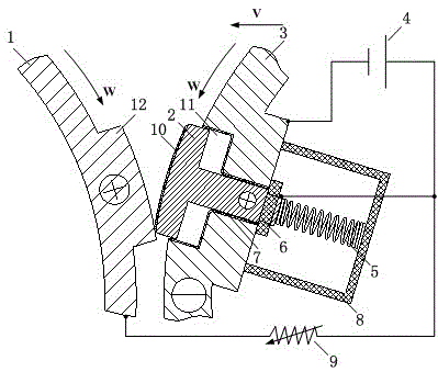
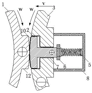
[0030] figure 2 , 3 , 4 are schematic diagrams when the auxiliary electrode is in different positions for electrolytic machining of a high boss with a height of 1-20 mm. When turning into the...


PUM


Abstract

The invention relates to an electrochemical machining bipolar electrode of a revolution body surface boss structure and the electrochemical machining method of the electrochemical machining bipolar electrode, and belongs to the technical field of electrochemical machining. The method is characterized in that a tool electrode is the bipolar electrode, according to different boss heights, an auxiliary electrode is arranged to be in a fixed and reciprocating motion manner, and a constant positive potential difference is applied to the auxiliary electrode and a workpiece positive pole through an electronic load in the machining process; and as the distance between the auxiliary electrode and a boss is short, according to the electric field distribution principle, the auxiliary electrode with the higher potential can effectively change electric field distribution on the surface of the boss in a machining zone, stray current on the surface of the boss is eliminated, and the effect of protecting the surface of the boss from dispersive corrosion is achieved.

Description

technical field [0001] The invention adopts the convex platform structure on the surface of a rotating body to electrolytically process bipolar electrodes and an electrolytic processing method thereof, belonging to the technical field of electrolytic processing. Background technique [0002] Electrolytic machining is the rapid removal of workpiece material using electrochemical reactions. Compared with traditional machining methods, electrolytic machining is non-contact machining, and has the advantages of no tool loss, no residual stress, no cold hardening, no plastic deformation, and low surface roughness during the machining process. Therefore, electrolytic machining is suitable for processing thin-walled parts, space-complex curved surfaces, and difficult-to-cut superalloy materials. [0003] As an important part of an aero-engine, the casing is a large thin-walled part with a complex concave-convex surface. The cost is high, the residual stress is large after proces...

Claims


Application Information

Patent Timeline
IPC IPC(8): B23H3/00B23H3/04
CPCB23H3/00B23H3/04
Inventor 朱增伟朱荻王登勇王宁峰
Owner NANJING UNIV OF AERONAUTICS & ASTRONAUTICS
Learn More