A circular rotating "receiving-returning" system suitable for rail transit

A rail transit and circular technology, applied in vehicle components, electric vehicles, transportation and packaging, etc., can solve the problems of insufficient utilization of carbon skateboard materials, untouched areas of carbon skateboards, etc., to save operating costs and eliminate stray Current, effect of preventing stray current corrosion

Active Publication Date: 2021-01-29
SOUTHWEST JIAOTONG UNIV
View PDF11 Cites 0 Cited by
  • Summary
  • Abstract
  • Description
  • Claims
  • Application Information

AI Technical Summary

Problems solved by technology

Aiming at the problems caused by stray currents, although there have been many countermeasures, such as strictly controlling the welding process of the train rail joints, strengthening the insulation measures between the train rails and the ballast bed, etc., the stray currents cannot be fundamentally eliminated. produce
[0006] At present, in order to make the carbon skateboard rub as evenly as possible during the operation of the electric locomotive, the contact line is generally erected in a "Z" shape, and the pantograph is often a "one" bow head. When the train starts running, The carbon sliding plate located at the pantograph head is in contact with the contact wire and slides relative to it. At this time, due to the "Z"-shaped erection of the contact wire, the contact wire will be in the "sweet zone" of about 60%-70% around the center of the carbon skateboard. "Slide back and forth relative to the carbon skateboard, which will make the carbon skateboard material not fully utilized. There are uncontacted areas on the carbon skateboard at both ends of the "non-sweet spot"

Method used


Image

  • A circular rotating "receiving-returning" system suitable for rail transit
  • A circular rotating "receiving-returning" system suitable for rail transit
  • A circular rotating "receiving-returning" system suitable for rail transit

Examples


Embodiment Construction

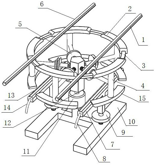
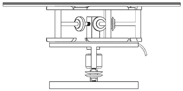
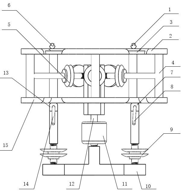
[0023] The present invention will be described in further detail below in conjunction with the accompanying drawings and specific embodiments. Such as figure 1 As shown, the present invention is applicable to the annular rotation "receiving-returning" system of rail transit, including the upper carbon slider 2 and the lower carbon slider 15; the upper carbon slider 2 and the lower carbon slider 15 include multiple sizes and The arc-shaped carbon sliders with equal radii, the upper carbon sliders 2 are arranged in a ring shape and separated from each other; the lower carbon sliders 15 are connected to the upper carbon sliders one by one through the carbon slider metal bracket 4 Below the block 2, each carbon slider metal bracket 4 is connected to the rotating shaft 12 through the carbon slider insulator 5; the rotating shaft 12 passes through the center of the ring and is connected to the output end of the rotating motor 14; it also includes The power supply line 6 and the ret...


PUM


Abstract

The invention discloses an annular rotating "receiving-returning" system suitable for rail transit, which includes a plurality of arc-shaped upper carbon sliders and lower carbon sliders, each upper carbon slider is arranged in a ring shape, and Separated from each other; each lower carbon slider is connected to the bottom of each upper carbon slider through a carbon slider metal bracket, and each carbon slider metal bracket is connected to the rotating shaft through an insulator; the rotating shaft passes through the center of the ring and connects to the rotating shaft. The motor output terminal; also includes the power supply line and the return line which are arranged above the upper carbon slider and are parallel to each other, and which are arranged under the lower carbon slider and which are in contact with the rotation and correspond to the power supply line and the return line respectively. A current-receiving support and a return support; the current-receiving support and the return support are connected to the current-receiving wire and the return wire respectively. The invention eliminates the phenomenon of stray current caused by the backflow of train rails, drives the carbon slider to rotate in a circle through a rotating motor, and ensures 100% utilization rate of the carbon slider.

Description

technical field [0001] The invention relates to the technical field of rail transit power supply systems, in particular to a circular rotating "flow receiving-return" system suitable for rail transit. Background technique [0002] With the overall development of my country's national economy and the continuous acceleration of urbanization, a safe, convenient and environmentally friendly electrified urban rail transit system is particularly important. The rapid development of high-speed railways has become an important transportation link between provinces and cities; as the core of intercity rail transit, the continuous development of urban rail transit has effectively alleviated the congestion of travel vehicles and provided convenience. At present, electric locomotives in urban rail transit mainly use DC traction power supply, and train rails are used as traction return branches. At present, it is temporarily impossible to ensure that the train rails are completely insul...

Claims


Application Information

Patent Timeline
Patent Type & Authority Patents(China)
IPC IPC(8): B60L5/20B60L5/22
CPCB60L5/205B60L5/22
Inventor 肖嵩叶智宗孟举童梦园赖新安李玉航吴京驰吴广宁高波杨雁李春茂曹保江
Owner SOUTHWEST JIAOTONG UNIV
Why Eureka
Try Eureka