Position controller and controlling method therefor

a technology of position controller and control method, which is applied in the direction of electric controller, program control, instruments, etc., can solve the problems of reducing the overall robustness of the control, causing resonance, etc., and reducing the possibility of mechanical resonance, the effect of preventing overshoot and reducing the feedforward

Active Publication Date: 2007-01-11
MITSUBISHI ELECTRIC CORP
View PDF9 Cites 26 Cited by
  • Summary
  • Abstract
  • Description
  • Claims
  • Application Information

AI Technical Summary

Benefits of technology

[0010] According to such position controller and the controlling method as above, when the control gain for preventing the overshoot is automatically adjusted, the overshoot is prevented with the gain based on the disturbance torque having been estimated, being operated so as to decrease the feedforward; therefore, the possibility of generating mechanical resonances is small, and because the compensation torque is not inverted in response to speed, the controlling does not oscillate near the nil speed; consequently, a highly robust position controller and a controlling method thereof can, be obtained.

Problems solved by technology

However, according to the viscous-friction-torque compensation method of the conventional technique, because, using an actual speed, torque is adjusted to be increased so as to compensate the friction torque, the friction compensation may induce resonance.
Furthermore, because the system compensates the friction torque toward positive, when an error is included in estimated friction-coefficient results, a problem has been found in that the overall robustness of the control is relatively low, for example, overshoot or undershoot occurs.

Method used


Image

  • Position controller and controlling method therefor
  • Position controller and controlling method therefor
  • Position controller and controlling method therefor

Examples


embodiment 1

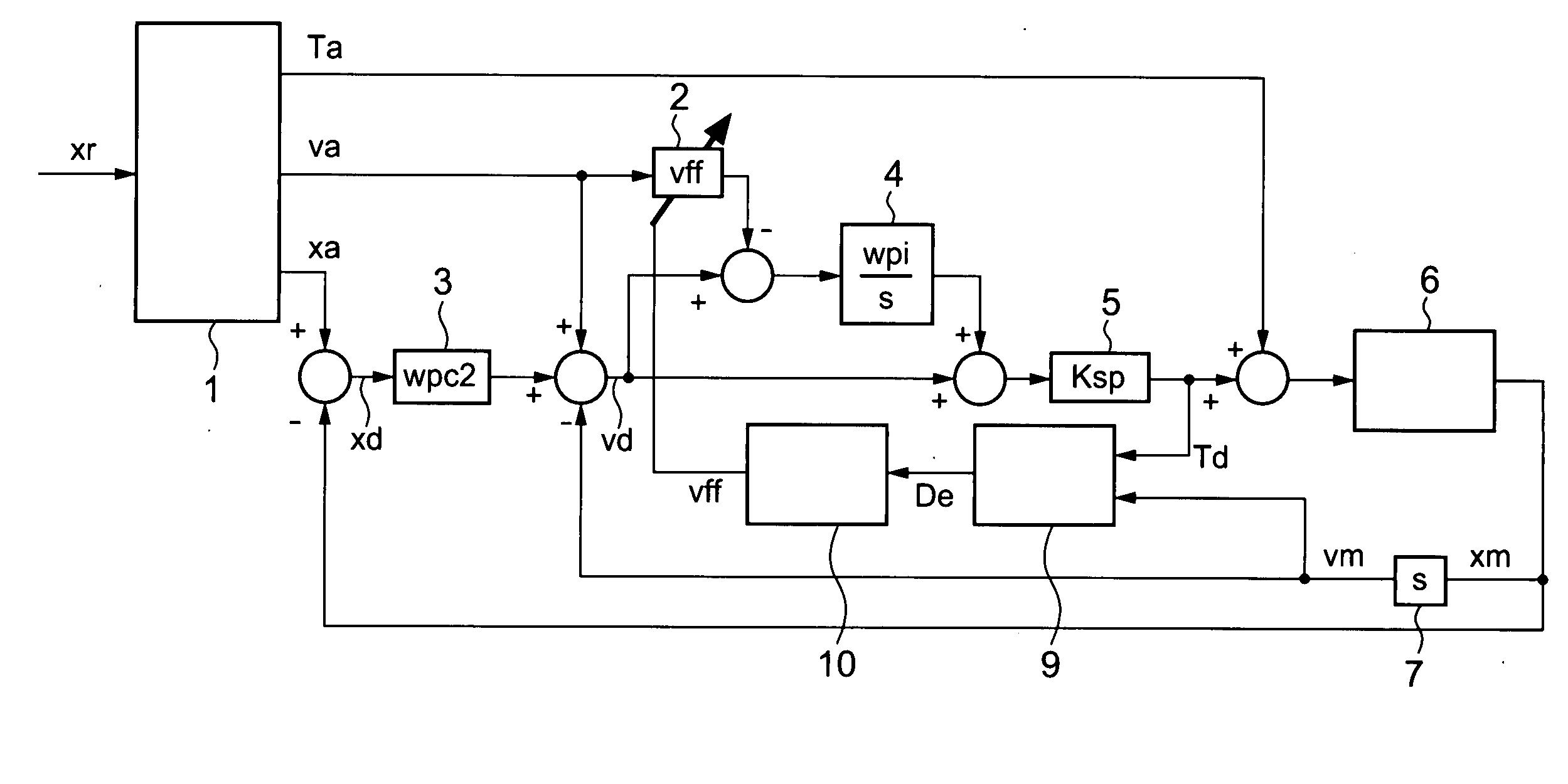
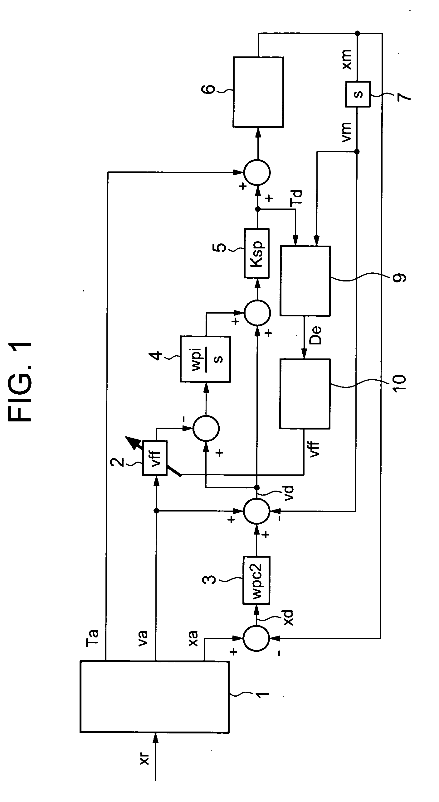
[0019]FIG. 1 represents a block diagram of entire Embodiment 1 according to the present invention. In the block diagram, feedback control is based on control using a position P (proportional) and speed PI (proportional and integral).

[0020] A configuration of Embodiment 1 is explained.

[0021] A model calculation means 1 inputs a command position xr and outputs model torque Ta, a model speed va, and a model position xa that are ideal for position control.

[0022] Because the model torque Ta, the model speed va, and the model position xa are outputted as models of suitable acceleration, speed, and position in response to the command position, various configurations can be considered for use in the model calculation means 1 corresponding to each model. A case is given in which the model position simply equals the command position, the model speed is given as a first-order differential of the command position, and the output of the model torque is set at “0”, or the model torque is given...

embodiment 2

[0038] In Embodiment 2 as contrasted to Embodiment 1, the output from the overshoot-prevention-gain calculation means 10 is mapped using a table corresponding to an actual condition of the plant 6.

[0039]FIG. 4 is a block diagram for the overshoot-prevention-gain calculation means 10 in Embodiment 2 according to the present invention. In Embodiment 1, position control has been explained in such cases in which the friction-coefficient estimated value De is approximately proportional to the speed.

[0040] However, depending on the structure of the plant 6, there also exist cases in which the friction-coefficient estimated value De irregularly varies without being proportional to the actual speed vm. In such cases, the speed-integral-term feedforward gain vff is not given by Equation 4 represented in Embodiment 1, but it is rather suitable that the friction-coefficient estimated values De corresponding to the speed-integral-term feedforward gains vff are prepared as a table in advance, ...

embodiment 3

[0042] In Embodiment 3, the estimated disturbance torque Td in Embodiment 1 is estimated using a disturbance observation means.

[0043]FIG. 5 illustrates an entire block diagram of Embodiment 3 according to the present invention. In FIG. 5, the same numerals as those in FIG. 1 denote the same or equivalent parts.

[0044] In Embodiment 1, when a correct inertia value is set in the model calculation means 1, and the control gain of the feedback system is high enough, it does not cause any problem in that a torque subtracted the model torque Ta from the torque command is estimated as the disturbance torque. In Embodiment 3, another case is represented in which, in order to estimate the disturbance torque Td as represented in FIG. 5, a disturbance observation means 8 estimates the disturbance-torque estimated value from an actual torque Tm inputted into the plant and the actual speed vm, then outputs to the friction-coefficient estimating means 9 the estimated value.

[0045] The disturbanc...


PUM


Abstract

An objective is to obtain a high robust position controller and a controlling method therefor, with respect to their technique in which control gain, in order to prevent an overshoot due to frictions, is most suitably adjusted. The position controller having a feedforward system includes: a friction-coefficient-estimated-value setting unit for setting arbitrary friction-coefficient-estimated-values; an overshoot-prevention-gain calculator for determining speed-integral-term feedforward gain, based on estimated friction-coefficient values set by the friction-coefficient-estimated-value setting unit; and a speed feedforward multiplying unit for calculating the product of the speed-integral-term feedforward gain multiplied by a feedforward command value that is based on a positional command; the multiplication product from the speed feedforward multiplying unit being used to reduce the feedforward term.

Description

TECHNICAL FIELD [0001] The present invention relates to position controllers and methods thereof for controlling positions in machinery systems such as machine tools and semiconductor manufacturing apparatus. BACKGROUND ART [0002] In position controllers, friction characteristics that targets to be controlled (hereinafter referred to as controlled targets) have in machinery systems vary greatly depending on temperature and across the ages; therefore, even if, taking into consideration the friction characteristics so that overshoot never happens, a gain most suitable for the controlled target is set, due to the varying of the friction characteristics, the overshoot may sometimes happen when the friction increases, or, on the contrarily, even if the overshoot does not happen when the friction decreases, it sometimes takes a longer time before the position has been decided. Therefore, in a machine in which the friction varies, in order to prevent overshoot in response to such friction ...

Claims


Application Information

Patent Timeline
Patent Type & Authority Applications(United States)
IPC IPC(8): G05B11/01G05B13/02G05B19/404G05D3/12H02P29/00
CPCG05B5/01G05B13/02G05B11/42
Inventor TERADA, KEIYOSHIDA, MASAHIKONAGANO, TETSUAKIIKEDA, HIDETOSHI
Owner MITSUBISHI ELECTRIC CORP
Why Eureka
Try Eureka