Centrifugal propulsion engine

a centrifugal and propulsion engine technology, applied in the direction of motors, belts/chains/gearings, etc., can solve the problems of inability to meet the needs of many applications, especially for satellite use, imbalance, inadvertent transformation of gravitational force into directional energy,

Inactive Publication Date: 2007-01-18
PEREZ DANIEL
View PDF2 Cites 18 Cited by
  • Summary
  • Abstract
  • Description
  • Claims
  • Application Information

AI Technical Summary

Benefits of technology

[0015] Each of the hub structures preferably include an assembly axle rotatably and engagingly fitted into the bearing mount. The centrifugal engine preferably additionally includes gear teeth along adjacent beveled edges of the first and second hub structures and a beveled linking gear engaging gear teeth along adjacent beveled edges of the first and second hub structures, constraining the first and second centrifugal assemblies to rotate in opposite directions. Each spoke preferably includes a spoke rack having an I-beam with a longitudinal series of rack gear teeth along one I-beam edge, and a rotatable drive rod substantially parallel and adjacent to the I-beam, and each mobile mass structure preferably includes a carriage which extends between and rides along the spoke rack and the spoke drive rod opposing ends of the bearing mount each have an annular series of gear teeth defining opposing first and second bevel

Problems solved by technology

These devices have been gravity dependent in their operation, which makes them unsuitable for many applications and particularly for use in satellites.
In one prior engine, mass is diverted from a gyroscopic path, or full rotational circle, to stay on one side of a 360 degree range of motion by mechanically swapping weights, from one of several consecutive, rotating arms to the next, and so on, creating an im

Method used


Image

  • Centrifugal propulsion engine
  • Centrifugal propulsion engine
  • Centrifugal propulsion engine

Examples


first preferred embodiment

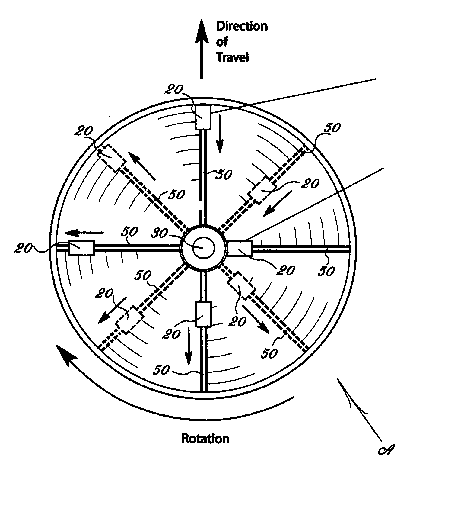
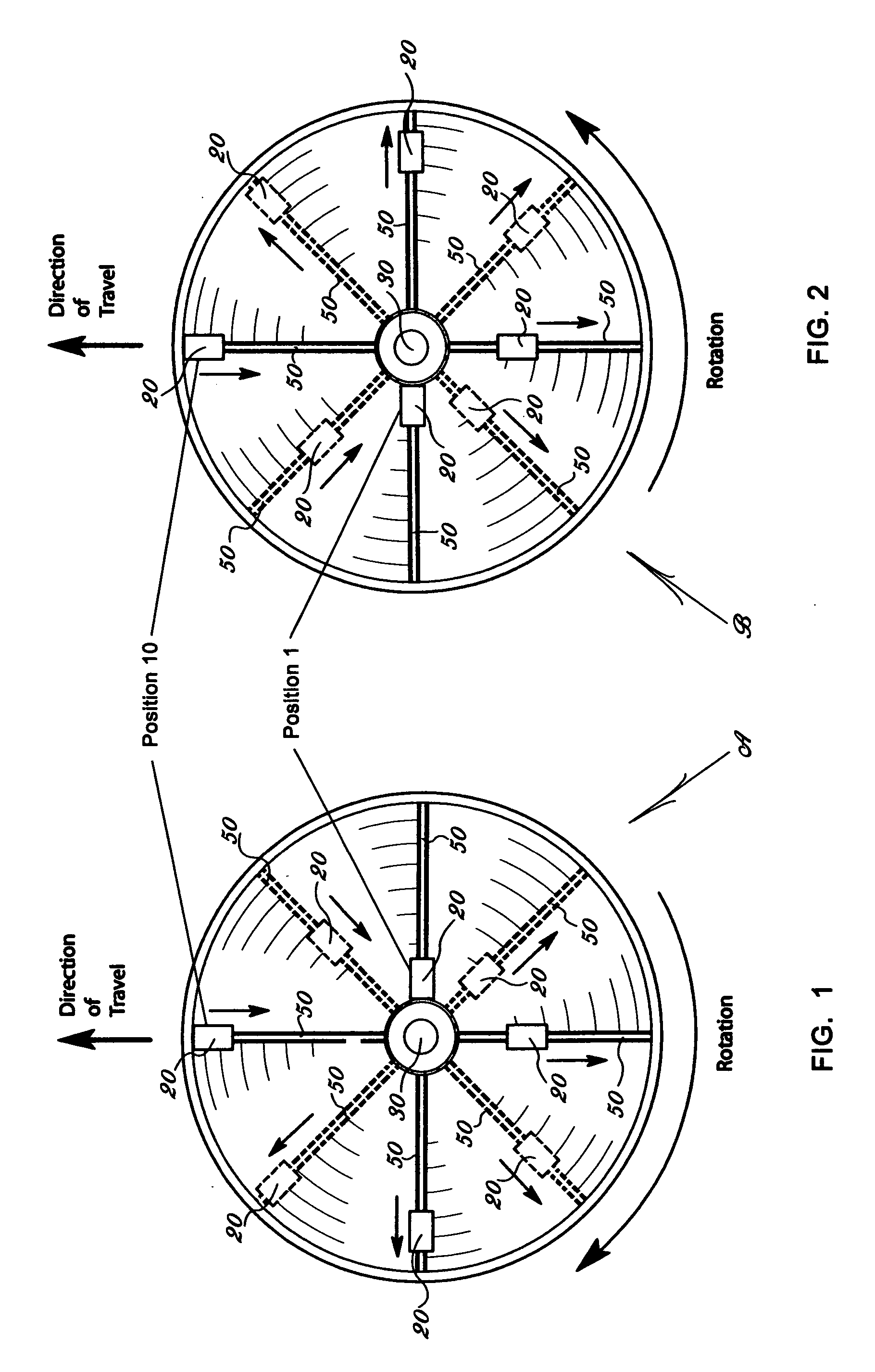
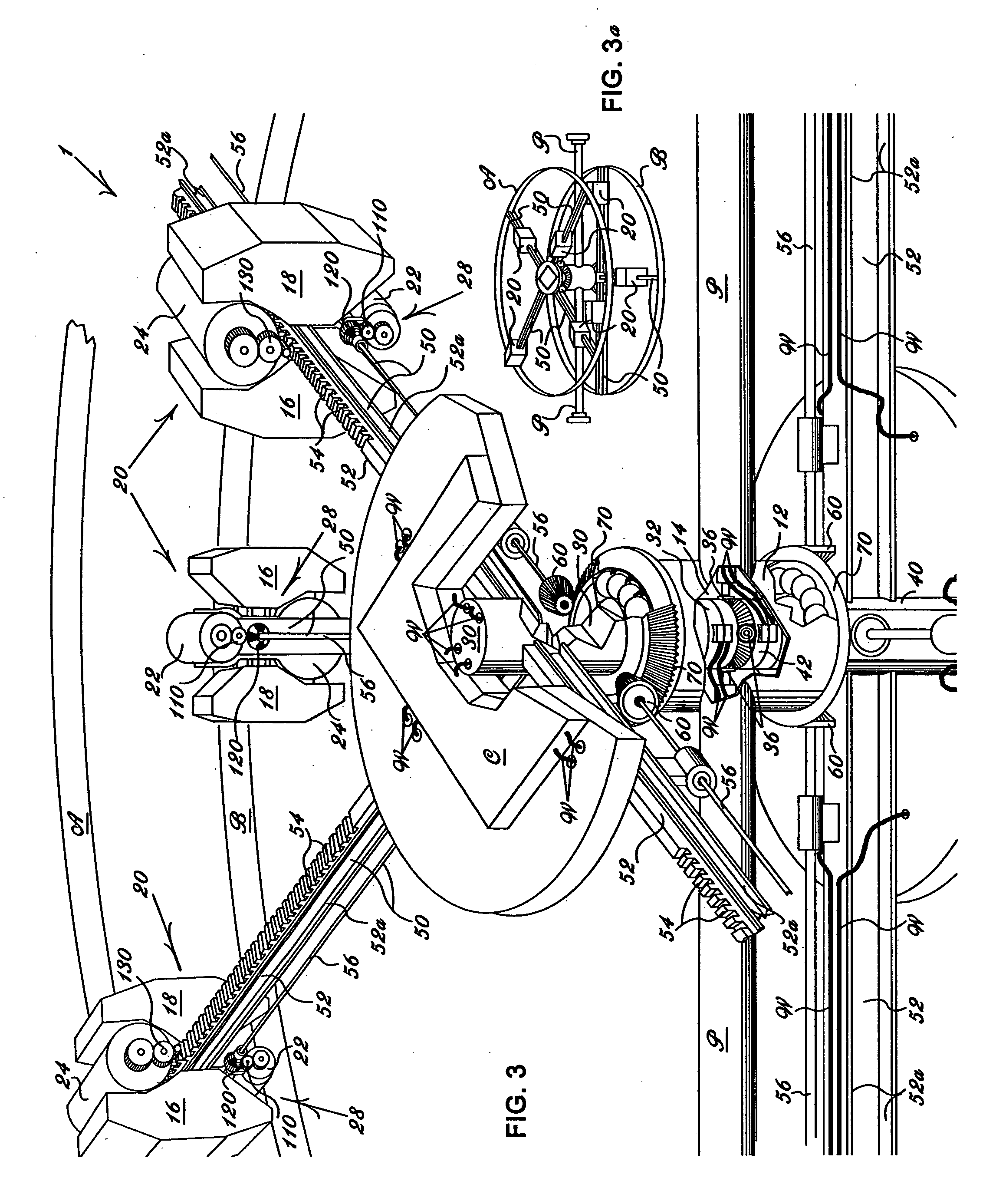
[0032] Referring to FIGS. 1-9, a centrifugal engine 10 is disclosed including first and second centrifugal assemblies A and B, respectively, having independent first and second assembly hub structures 30 and 40, each hub structure 30 and 40 being rotatably mounted to a common bearing mount 12 to rotate co-axially and in opposite directions. The bearing mount 12 passes through and is fixedly secured relative to a partition structure P such as a satellite wall which extends between and is generally parallel to the first and second centrifugal assemblies A and B. Several spokes 50 protrude radially from each hub structure 30 and 40 and a mobile mass structure 20 is slidably mounted to each spoke 50. A power source preferably in the form of battery packs 16 and 18 delivers electrical energy to rotate each hub structure 30 and 40 and attached spokes 50 relative to the bearing mount 12, and also to sequentially move the mobile mass structures 20 longitudinally along the spokes 50 and radi...


PUM


Abstract

A centrifugal engine includes first and second centrifugal assemblies having independent assembly hub structures, each hub structure being rotatably mounted to a common bearing mount to rotate co-axially and in opposite directions; several spokes protruding radially from each hub structure; a mobile mass structure slidably mounted to each spoke; a rotation motor; several mass structure displacement motors, each for displacing one mobile mass structure along a corresponding spoke; a power source delivering electrical energy to the rotation motor to rotate each hub structure and attached spokes relative to the bearing mount, and also to the mass structure displacement motor to sequentially move the mobile mass structures longitudinally along the spokes and radially away from the given the hub structure and then rapidly toward the hub structure at a repeating rotational position to impart linear force to the assembly.

Description

BACKGROUND OF THE INVENTION [0001] 1. Field of the Invention [0002] The present invention relates generally to the field of devices for converting electrical energy into kinetic energy. More specifically the present invention relates to a centrifugal engine including first and second centrifugal assemblies having independent assembly hub structures, each hub structure being rotatably mounted to a common bearing mount to rotate co-axially and in opposite directions. The bearing mount passes through and is fixedly secured relative to a partition structure such as a satellite wall which extends between and is generally parallel to the first and second centrifugal assemblies. Several spokes protrude radially from each hub structure and a mobile mass structure is slidably mounted to each spoke. A power source delivers electrical energy to rotate each hub structure and attached spokes relative to the bearing mount, and also to sequentially move the mobile mass structures longitudinally al...

Claims


Application Information

Patent Timeline
IPC IPC(8): F16H27/04
CPCF03G3/00Y10T74/18536F03H99/00
Inventor PEREZ, DANIEL
Owner PEREZ DANIEL
Why Eureka
Try Eureka