Fire resistant electrical cable splice

Active Publication Date: 2007-01-18
RSCC WIRE & CABLE LLC
View PDF24 Cites 8 Cited by
  • Summary
  • Abstract
  • Description
  • Claims
  • Application Information

AI Technical Summary

Problems solved by technology

Presently, non fire-rated electrical wires are at risk in a fire-related emergency.
Non fire-rated wiring is not designed to sustain operation at high temperatures.
Non fire-rated wiring insulation will quickly degrade in a high temperature environment as may exist in a fire.
However, all of these fire-rated electrical cables are limited in that splicing the electrical cables in the field (a location where the wiring is performed) negates the fire rating.
More simply, splicing technology has not been developed that reliably prevents a fire-rated electrical cable from breaking down at the splice in a high temperature environment.
This code limitation often forces electrical contractors to run hundreds of feet of electrical cable without interruption.
Pulling long runs of fire-rated electrical cable is more labor intensive and, if performed improperly, can lead to damaging the fire-rated electrical cables.
In fact, currently no fire-rated electrical cable is approved for field splicing.
Splicing Mineral Insulated (“MI”) electrical cable can only be performed at factories because of the complex nature of splicing mineral insulated electrical cable.
Application of the lesser impact hose stream test is limited to fire alarm electrical cable.
Thus, a heretofore unaddressed need exists in the industry to address the aforementioned deficiencies and inadequacies.

Method used


Image

  • Fire resistant electrical cable splice
  • Fire resistant electrical cable splice
  • Fire resistant electrical cable splice

Examples


Embodiment Construction

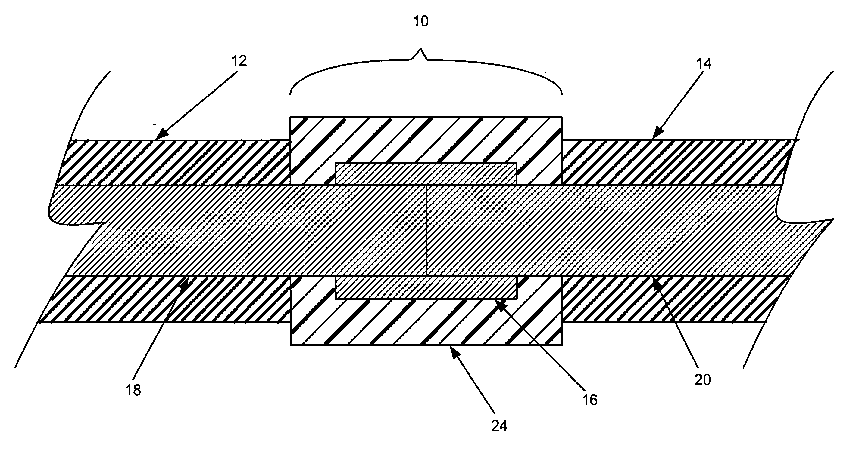
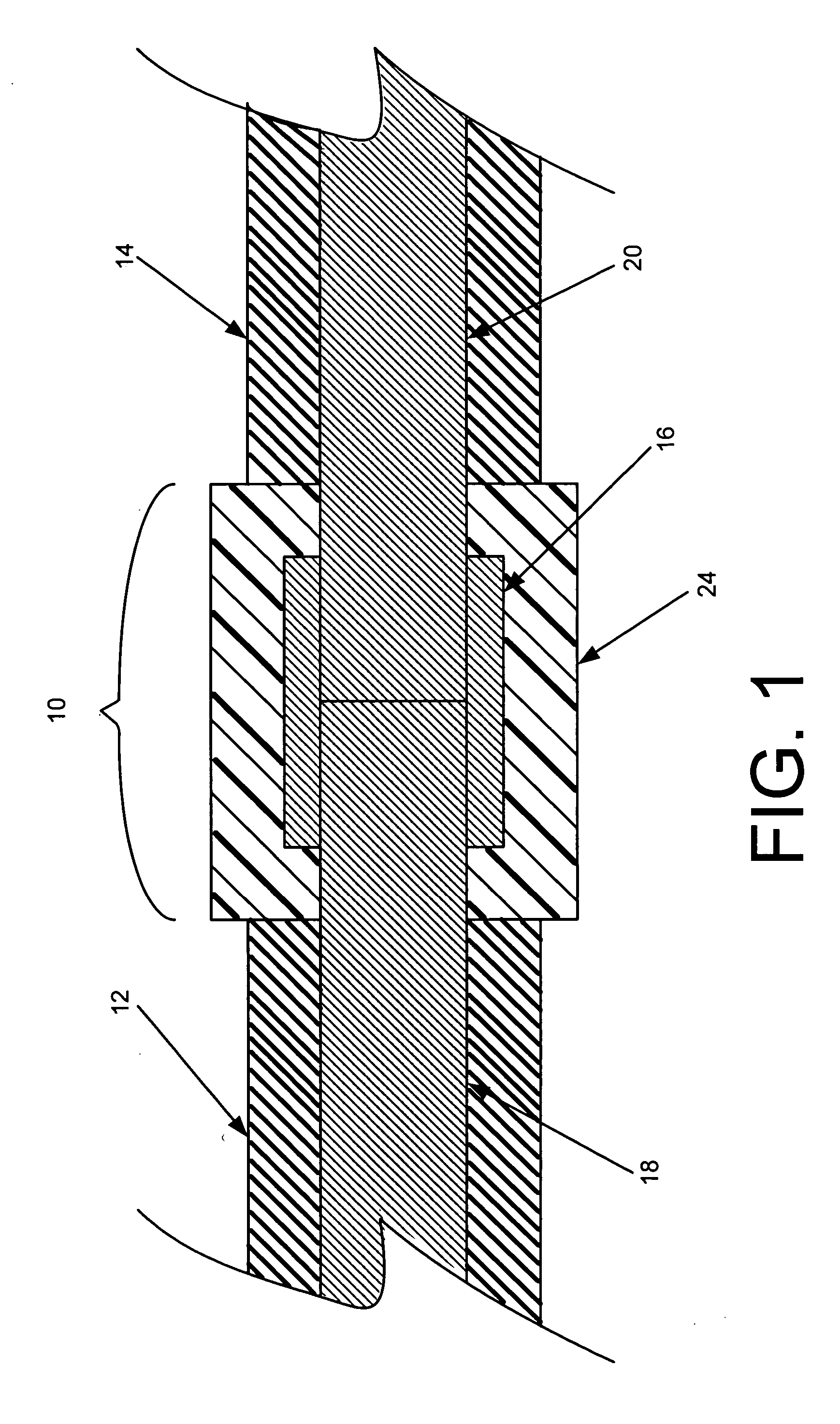
[0019]FIG. 1 is a cross-sectional view of two electrical cables 12, 14 connected by a fire resistant electrical cable splice 10, in accordance with a first exemplary embodiment of the invention. The two electrical cables 12, 14 are joined by at least one connection 16. The connection 16 is formed by at least one conductor 18, 20 from each of the electrical cables 12, 14, which are connected mechanically and electrically. An insulating polymer 24 is substantially applied over the connection 16. The insulating polymer 24 should be electrically nonconductive at temperatures consistent with the presence of a fire.

[0020] It is anticipated that the electrical cables 12, 14 will be fire resistant electrical cables, although the fire resistant electrical cable splice 10 may be used for other types of electrical cables. If fire resistant, the electrical cables 12, 14, for instance, may be mineral insulated electrical cables, polymeric ceramifiable electrical cables, or other fire-rated elec...


PUM


Abstract

The fire resistant electrical cable splice joins two electrical cables. The two electrical cables are joined by at least one connection. The connection is formed between at least two conductors, at least one conductor from each of the electrical cables. The connection connects the conductors mechanically and electrically. An insulating polymer, which is electrically nonconductive at temperatures normally associated with the presence of a fire, is substantially applied over the connection. The insulating polymer may be a ceramifiable silicone rubber.

Description

FIELD OF THE INVENTION [0001] The present invention is in the field of electrical cable. More specifically, the present invention is in the field of fire resistant electrical cable. BACKGROUND OF THE INVENTION [0002] The availability of electrical devices during fires can have lifesaving implications. Exit signs and emergency lights help light where to go in an emergency. Hard-wired fire alarms alert people to an emergency situation. In hospitals and nursing homes, electricity is needed to power devices that are directly in use to sustain life. For these and other reasons, government regulations in numerous countries now specify that essential electrical circuits be protected in order to ensure that the electrical system maintain an operating condition during a fire to ensure the safety of persons inside the building and also to permit fire-fighting personnel to be more efficient in controlling and extinguishing fires. For example, in certain locations, such as high-rise buildings, ...

Claims


Application Information

Patent Timeline
IPC IPC(8): H02G15/08
CPCH01R4/726H02G15/08H01R13/527
Inventor KONNIK, ROBERT
Owner RSCC WIRE & CABLE LLC
Why Eureka
Try Eureka