Locator with removable antenna portion

a technology of locators and antennas, applied in audible signalling systems, instruments, using reradiation, etc., can solve the problems of storing several locators on the service truck, requiring several locators, and requiring several locators in a reasonable fashion

Active Publication Date: 2007-01-18
BUSAN TRANSPORTATION CORPORATION
View PDF11 Cites 73 Cited by
  • Summary
  • Abstract
  • Description
  • Claims
  • Application Information

AI Technical Summary

Benefits of technology

[0013] These and other embodiments are discussed mor

Problems solved by technology

As such, locators may be difficult to store or ship in a reasonable fashion.
Further, several locators may be required on a truck because

Method used


Image

  • Locator with removable antenna portion
  • Locator with removable antenna portion
  • Locator with removable antenna portion

Examples


Embodiment Construction

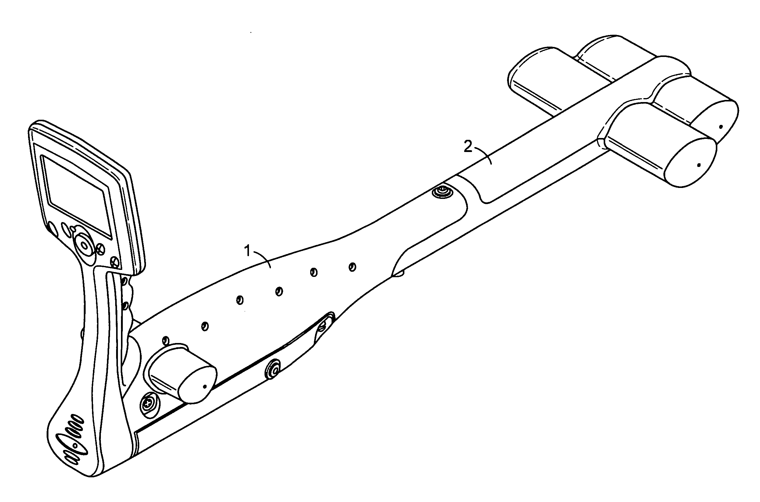
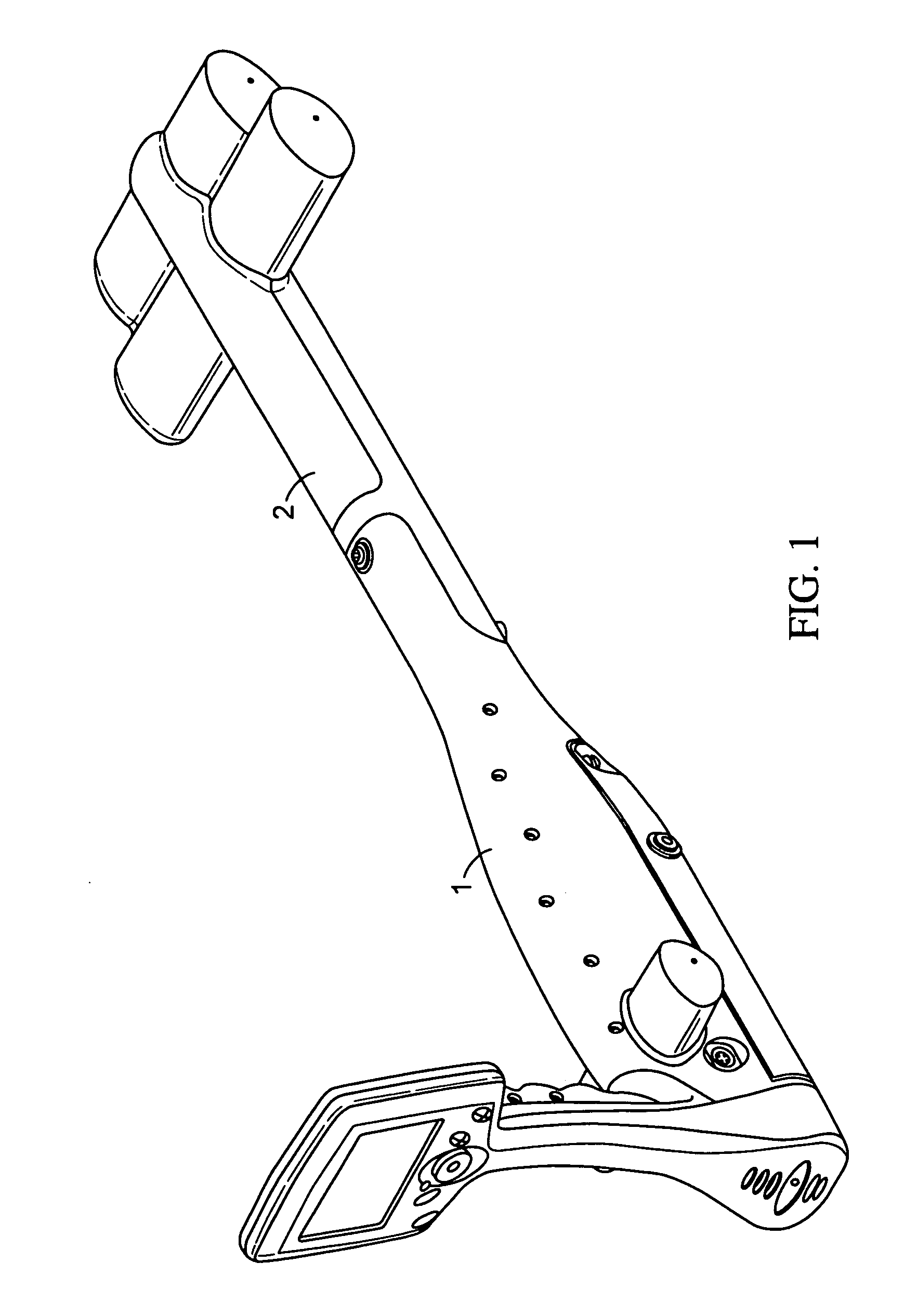
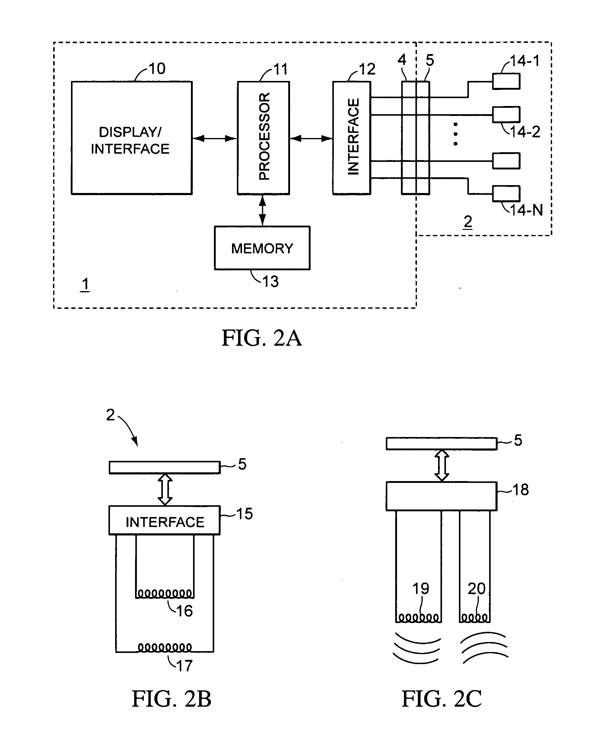
[0020] A locator according to embodiments of the present invention includes a make and break connection between a base electrical and mechanical enclosure and a variety of RF antenna modules. The RF modules can allow the base unit a range of functionality, such as, for example, operating as a line locator or a marker locator. The joint between the base electrical and mechanical enclosure and the RF modules can be mechanically suitable for the range of operating environments required for commercial line and marker location. The joint can be robust and environmentally sealed. The modular approach to a system that is both RF and digital brings utility advantages to the end user and improves the ability of the manufacturer to iterate products. The modular approach allows a flexible base platform to operate with a wide variety of different RF modules, for example a line locator antenna or a marker locator antenna.

[0021]FIG. 1 illustrates a locator according to some embodiments of the pr...


PUM


Abstract

A locator is disclosed that includes a base module and an antenna module. The base module and antenna module are coupled both mechanically and electrically at a joint. Such an arrangement allows for easy stowage and shipment of the locator as well as the ability, by interchanging antenna modules, to provide multi-functional locators.

Description

RELATED APPLICATIONS [0001] This application claims the benefit of Provisional Application No. 60 / 688,489, filed Jun. 7, 2005, which is hereby incorporated by reference in its entirety.BACKGROUND [0002] 1. Field of the Invention [0003] The present invention is related to underground structure locators, and in particular to a line locator or marker locator with a removable antenna portion. [0004] 2. Background of the Invention [0005] Line locators are utilized in determining the location of underground pipes and cables. In general, a line locator includes one or more antennas positioned to detect the magnetic field emitted from an underground cable or pipe. The underground cable or pipe may be coupled to a transmitter so that current flowing through the cable or pipe generates the magnetic field that is detected by the locator. [0006] Marker locators are utilized in determining the location of buried resonant markers. Markers are often laid in proximity to a cable or pipe. For exampl...

Claims


Application Information

Patent Timeline
IPC IPC(8): G01V3/08
CPCG01V3/15
Inventor STAPLES, GREGCROTHALL, GEORGEWAITE, JAMES W.
Owner BUSAN TRANSPORTATION CORPORATION
Why Eureka
Try Eureka