Automatically rotatable lamp ball

a lamp ball and automatic technology, applied in the field of automatic rotatable lamp balls, can solve the problems of not being able to appeal to consumers, especially children, and achieve the effect of improving the safety of children

Inactive Publication Date: 2007-01-18
LIN LISA LI HSIANG
View PDF3 Cites 9 Cited by
  • Summary
  • Abstract
  • Description
  • Claims
  • Application Information

AI Technical Summary

Benefits of technology

[0005] The objective of the invention is to offer an automatically rotatable lamp ball including a power unit, a lamp arm and a transmission unit with a conducting unit. The power unit is composed of a front half unit and a rear half unit, having its interior installed with batteries, a motor and a switch member for controlling power conduction of the batteries. The motor is provided with a downward shaft for driving two rollers assembled at one side of the power unit to rotate after reducing speed. The power unit has the other side assembled with a no-power roller. The motor is further provided with an upward shaft for driving a gear with a center shaft hole to rotate after reducing speed. The lamp arm is composed of a front half arm shell and a rear half arm shell and divided into a center arm body positioned above the power unit and two side arm bodies respectively extending downward from the center arm body to two opposite sides. The center arm body of the lamp arm is formed with a center chamber in the interior for receiving a circuit board and bored with a hollow shaft groove extending downward. The two side arm bodies have their interiors respectively formed with a side chamber for installing therein with a plurality of LEDs that are electrically connected with the circuit board. The transmission unit is provided with a conductive center shaft having a part of its outer side fitted around with an insulating sleeve mounted around with a conducting shaft tube. The center shaft, the insulating sleeve and the conducting shaft tube together make up a rod-shaped conducting unit to be inserted through the center shaft hole of the gear of the power unit and firmly positioned in the hollow shaft groove under the center chamber of the lamp arm for supporting and driving the lamp arm to rotate and serving as a rotation axis of the lamp arm. The power unit is disposed with two conducting brush members respectively positioned in its front and rear half unit. One end of the two conducting brush members serves as one electrode of electricity and the other end respectively contacts with the conducting center shaft and the conducting shaft tube, which are electrically connected with the circuit board in the main chamber of the lamp arm. The integral body of the power unit and the lamp arm is placed in the interior of a transparent outer casing and actuated to rotate therein for pushing the outer casing to roll freely. Thus, changeable flickering lights given out by the LEDs on the lamp arm can be seen through the transparent outer casing and, by visual persistence, the stereoscopic light patterns or letters can be presented before viewers,

Problems solved by technology

In general, some spherical toys are provided with a power unit and able to roll automatically, but unable to actuate the radial arms appended thereon to rotate and give out bright lights synchronously, while other spherical toys are able to be rolled and give out flickering lights, such as shining yo-yos, but unable to roll automatically and provided with no radial arms to rotate synchronously for increasing entertaining effect.
For the present, technology has been developed and toys have become more manifold than ever; therefore, toys must be exclusively original, interesting and diversiform; otherwise, they cannot appeal to consumers, especially children.

Method used


Image

  • Automatically rotatable lamp ball
  • Automatically rotatable lamp ball
  • Automatically rotatable lamp ball

Examples


Embodiment Construction

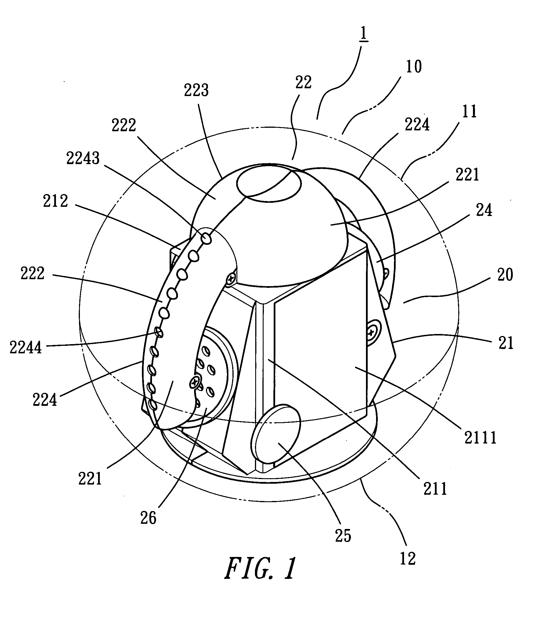
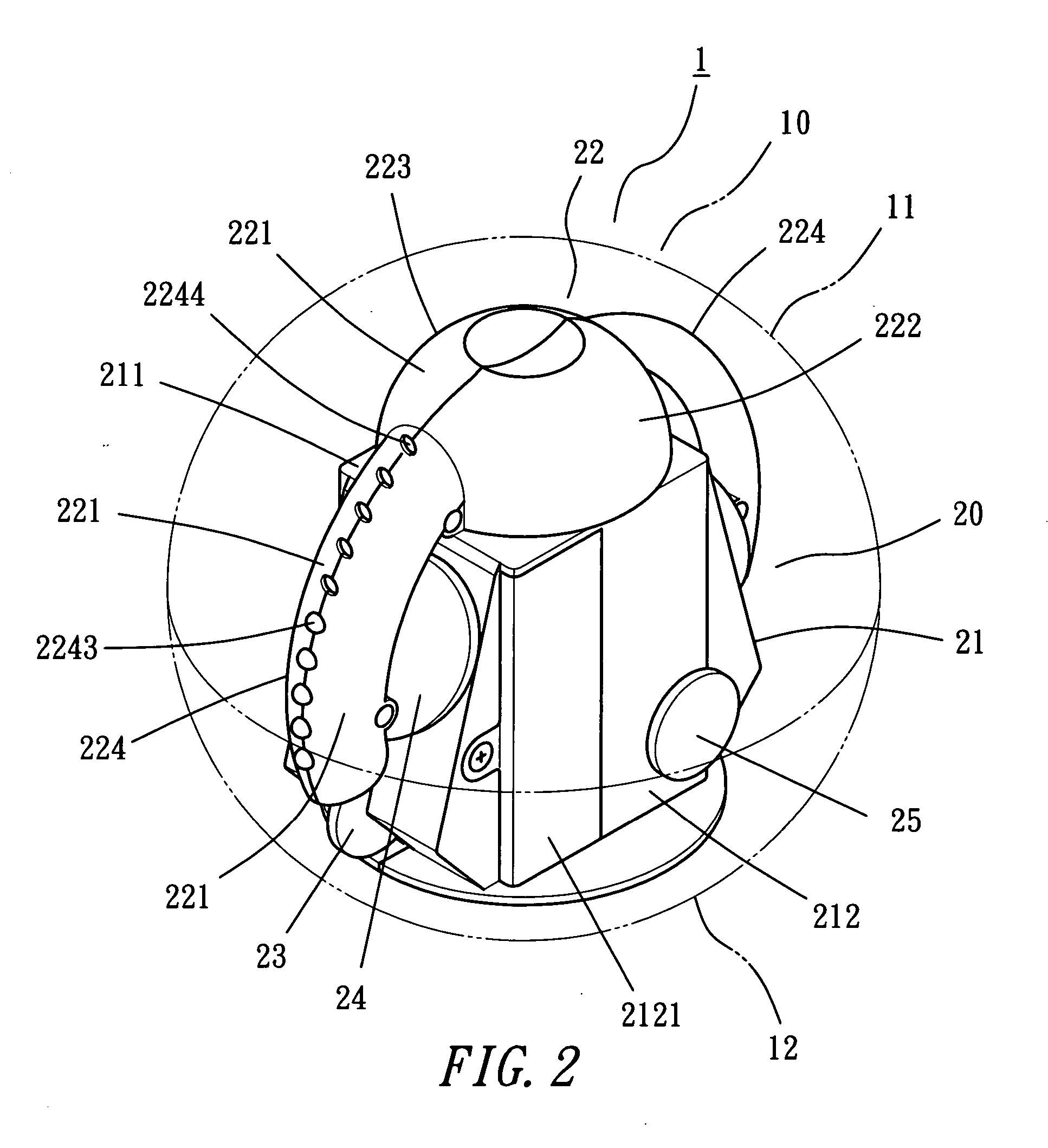
[0016] A preferred embodiment of an automatically rotatable lamp ball 1, as shown in FIGS. 1 and 2, includes a spherical outer casing 10 and a power-and-lamp arm unit 20.

[0017] The spherical outer casing 10 made of transparent material is composed of two half casings 11 and 12 respectively and correspondingly provided with plural L-shaped engage slots 111 and projecting members 121, as shown in FIG. 3. The mutually combining edges of the two half casings 11, 12 can be closely combined together by vertically engaging the projecting members 121 in the L-shaped engage slots 111 and then moving the projecting members 121 horizontally. The two half casings 11, 12 can be disengaged from each other by operating steps reverse to those mentioned above. Apart from this way of mutual engagement of the engage slots 111 and the projecting members 121, the two half casings 11, 12 can also be combined together in another way of screwing or clasping. Alternate combinations of the two half casings ...


PUM


Abstract

An automatically rotatable lamp ball includes a power unit provided with a motor having its downward shaft driving two rollers to rotate and its upward shaft driving a lamp arm to rotate. The lamp arm is disposed thereon with a plurality of LEDs, and the integral body of the power unit and the lamp arm is received in the interior of a transparent outer casing and actuated to rotate therein for pushing the outer casing to roll freely at the same time. When the lamp arm is actuated to rotate, the LEDs installed thereon will simultaneously give out flickering lights in sequence and at intervals and, due to visual persistence, presenting freely movable stereoscopic light patterns or letters. So the invention is innovative and exclusively original in structure and having excellent entertaining effect.

Description

BACKGROUND OF THE INVENTION [0001] 1. Field of the Invention [0002] This invention relates to an automatically rotatable lamp ball, particularly to one provided with rollers and a lamp arm able to be rotated and give out bright lights at the same time. After the lamp ball is placed in the interior of a transparent outer casing, the whole outer casing can be driven by the rollers to roll and move forward freely, and LEDs arranged on the lamp arm can be controlled by the IC programs inside the lamp ball to give out flickering lights in sequence and at intervals. By rotation of the lamp arm and due to visual persistence, the automatically rolling stereoscopic lights will be seen, offering viewers an exclusively original and surprising visual feeling. [0003] 2. Description of the Prior Art [0004] Nowadays, there are various kinds of automatically rolling spherical toys, such as disclosed in a Taiwan patent No. 277343, titled “Improved Structure For Rolling Toys”, and No. 294052, titled ...

Claims


Application Information

Patent Timeline
Patent Type & Authority Applications(United States)
IPC IPC(8): F21V21/30
CPCA63B43/04A63B43/06Y10S362/806A63H33/22Y10S362/80A63H33/005
Inventor LIN, LISA LI-HSIANG
Owner LIN LISA LI HSIANG
Why Eureka
Try Eureka