Imaging apparatus, image processing device, and control method

a technology of image processing device and control method, which is applied in the direction of image analysis, instruments, television systems, etc., can solve problems such as possible blurring, and achieve the effect of high accuracy

Active Publication Date: 2018-06-28
CANON KK
View PDF5 Cites 9 Cited by
  • Summary
  • Abstract
  • Description
  • Claims
  • Application Information

AI Technical Summary

Benefits of technology

[0008]According to the present invention, it is possible to detect a mo...

Problems solved by technology

If a velocity of panning performed by a photographer in accordance with a motion of the object is not appropriate, there...

Method used


Image

  • Imaging apparatus, image processing device, and control method
  • Imaging apparatus, image processing device, and control method
  • Imaging apparatus, image processing device, and control method

Examples


first embodiment

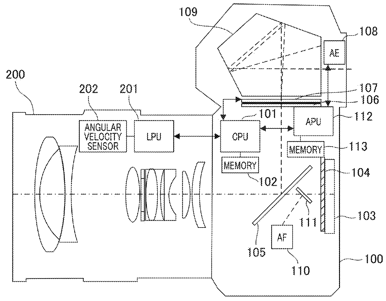
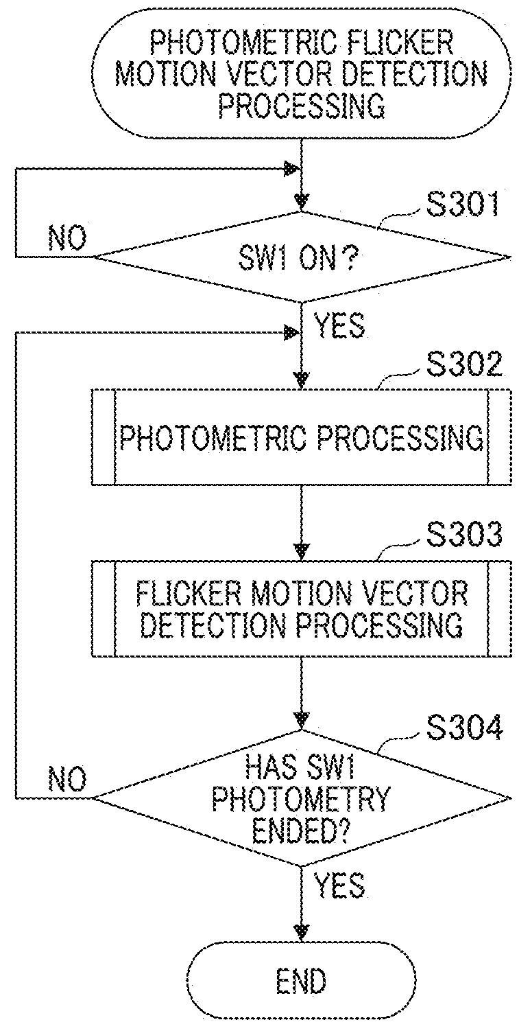
[0045]Hereinafter, a first embodiment of the present invention will be described. FIG. 3 is a flowchart of photometric flicker motion vector detection processing in the present embodiment. The following processing is realized by a CPU of the camera control unit 101 and the APU 112 reading a program from a memory and executing the program. First, in S301, a user operates a photographing button, and processing for determining whether an ON state of SW1 is detected is performed. If it is determined that SW1 is in an ON state, the procedure proceeds to processing of S302. If it is determined that SW1 is not in an ON state, determination processing of S301 is repeated.

[0046]In S302, photometric processing for determining an exposure at the time of photographing is executed. The photometric processing will be described using a flowchart of FIG. 4. Next, in S303, flicker motion vector detection processing is executed. Processing for detecting whether a object is under a flicker light sourc...

second embodiment

[0066]A second embodiment of the present invention will be described. In the present embodiment, processing for performing motion detection with high accuracy under a flicker light source by using flicker detection information in response to a decrease in motion detection accuracy under a flicker light source will be described. Description of material the same as in the first embodiment will be omitted and differences will be mainly described in the present embodiment. A method of omitting such description is also the same as in embodiments described below.

[0067]Flicker motion vector detection processing (S303 of FIG. 3) of the present embodiment will be described with reference to a flowchart of FIG. 10. In S1001, accumulation FV processing is performed in the same manner as in S501 of FIG. 5. Time information (Ts1, Ts2, Ts3, and the like) is held in the memory 113 due to a timer for measuring time. In S1002, read FV processing is performed in the same manner as in S502 of FIG. 5.

[...

third embodiment

[0088]Next, a third embodiment of the present invention will be described. In the second embodiment, motion vector detection using an image corrected by gain multiplication is described, but there is concern that image noise may occur due to the gain multiplication. If the image noise is large, accuracy in motion detection may decrease. Therefore, in the present embodiment, processing for performing motion detection with high accuracy using flicker detection information without generating image noise under a flicker light source is described. A case in which an amplitude of the brightness of a flicker light source is larger than in a case under a flicker light source described in the above embodiments is described as an example.

[0089]FIGS. 18A to 18D are diagrams which describe a change in brightnesses of photometric images FV captured in a flicker motion vector detection processing period under a flicker light source. In a graph of FIG. 18A, the vertical axis represents brightness ...


PUM


Abstract

An imaging apparatus includes a photometric sensor, and can continuously acquire a plurality of images by a single imaging operation. A CPU for image processing and an arithmetic operation acquires image data output by a photometric sensor and performs photometric processing. The CPU determines presence or absence of a flicker light source using a plurality of pieces of acquired image data, and calculates a motion vector of an object by comparison of image data. If it is determined that there is a flicker light source in a photographing environment, gain adjustment is performed on the basis of a result of flicker detection so as to have a brightness of an image suitable for detection of a motion vector, and the motion vector is calculated using image data after gain adjustment.

Description

BACKGROUND OF THE INVENTIONField of the Invention[0001]The present invention relates to a technology of detecting brightness under a flicker light source and a technology of detecting a motion amount of an object.Description of the Related Art[0002]An imaging apparatus such as a single-lens reflex camera performs photometry by processing image signals acquired by a photometric sensor before photographing. A light source such as a fluorescent lamp repeats flickering under an alternating current, a so-called flickering phenomenon occurs, and there is a photographing system which detects a flickering cycle.[0003]On the other hand, in a panning as a photographing technology which expresses a sense of speed of an object (moving object), a photographer performs panning of a camera in accordance with a motion of the object, and aims to capture a still object image and a background-flowing image. If a velocity of panning performed by a photographer in accordance with a motion of the object ...

Claims


Application Information

Patent Timeline
IPC IPC(8): G06T7/246H04N5/243H04N5/232H04N5/235
CPCG06T7/248H04N5/243H04N5/23212H04N5/2351H04N5/23222H04N23/67H04N23/6815H04N23/6811H04N23/6812H04N23/745H04N23/76H04N23/71H04N23/64
Inventor SHINTANI, TAKUYA
Owner CANON KK
Why Eureka
Try Eureka