Orthopedic clamping hook assembly

a hook and orthopedic technology, applied in the field of orthopedic hook assembly, can solve the problem of not being able to meet the needs of thin bone areas

Active Publication Date: 2007-01-18
DEPUY SPINE SARL
View PDF99 Cites 91 Cited by
  • Summary
  • Abstract
  • Description
  • Claims
  • Application Information

AI Technical Summary

Problems solved by technology

The orthopedic clamping hook assembly allows for rigid fixation to the occiput or other location without use of bone anchoring screws, which may not be feasible in thin bone areas.

Method used


Image

  • Orthopedic clamping hook assembly
  • Orthopedic clamping hook assembly
  • Orthopedic clamping hook assembly

Examples


Embodiment Construction

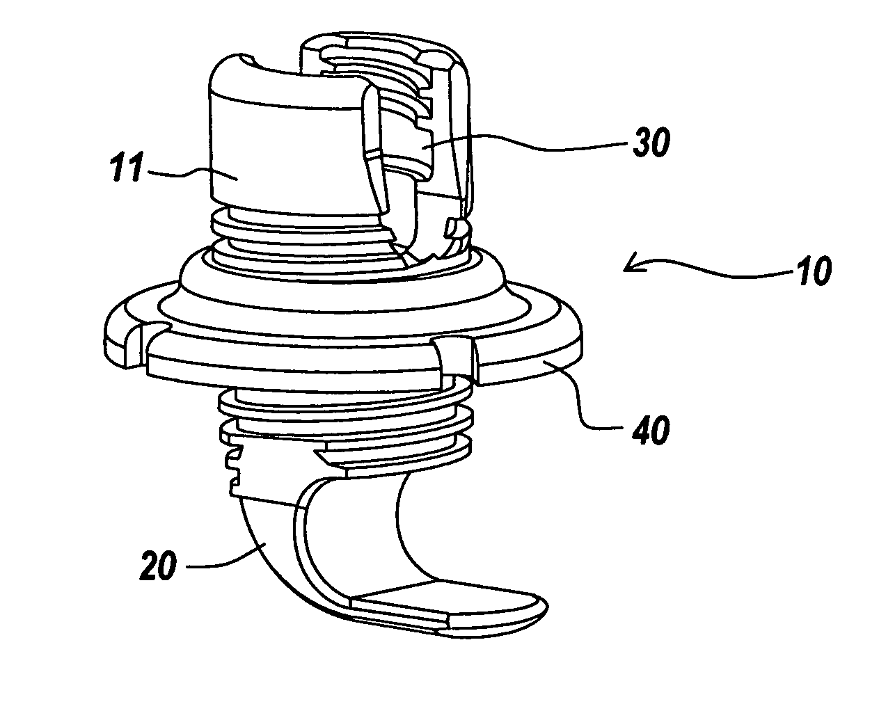
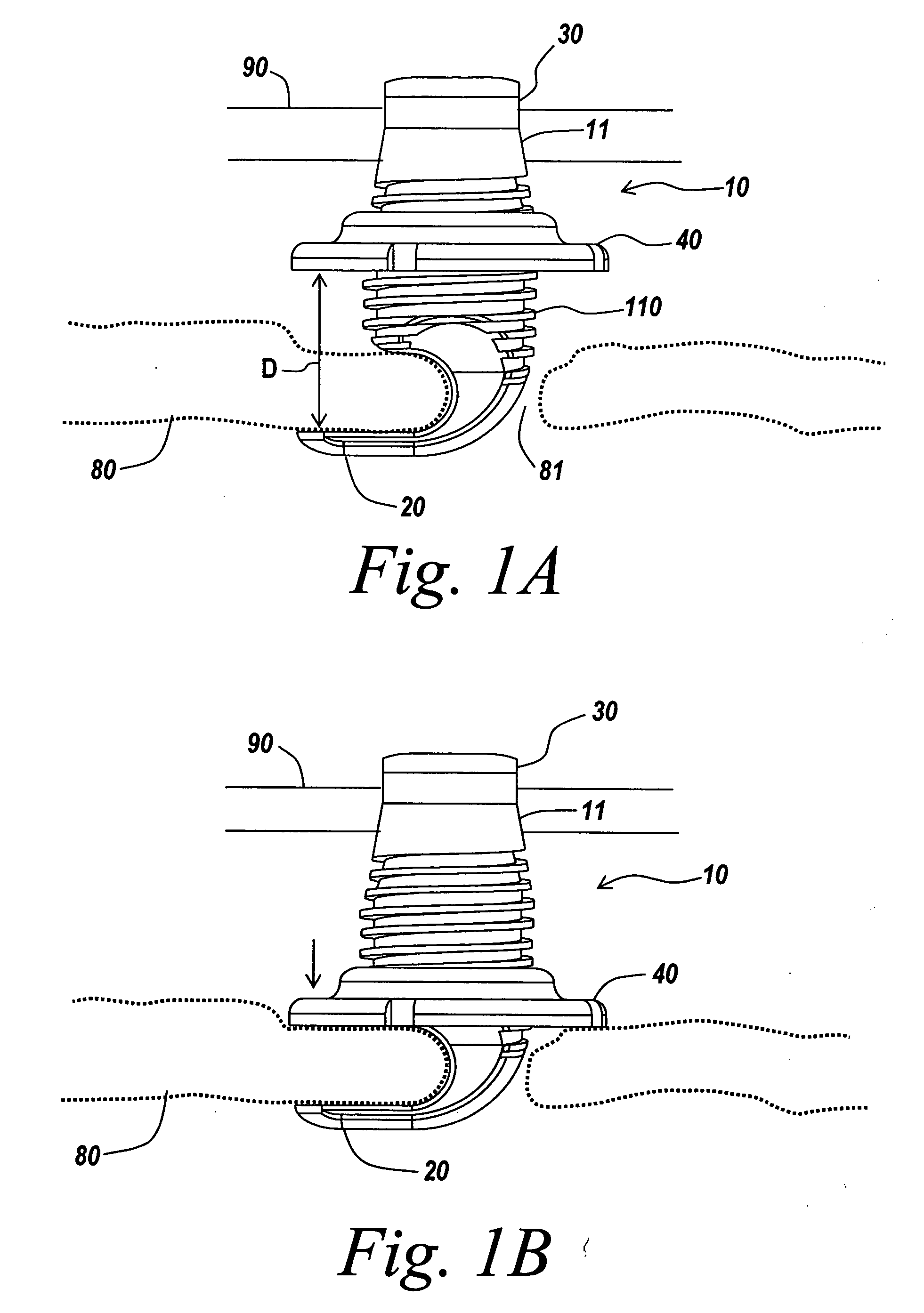
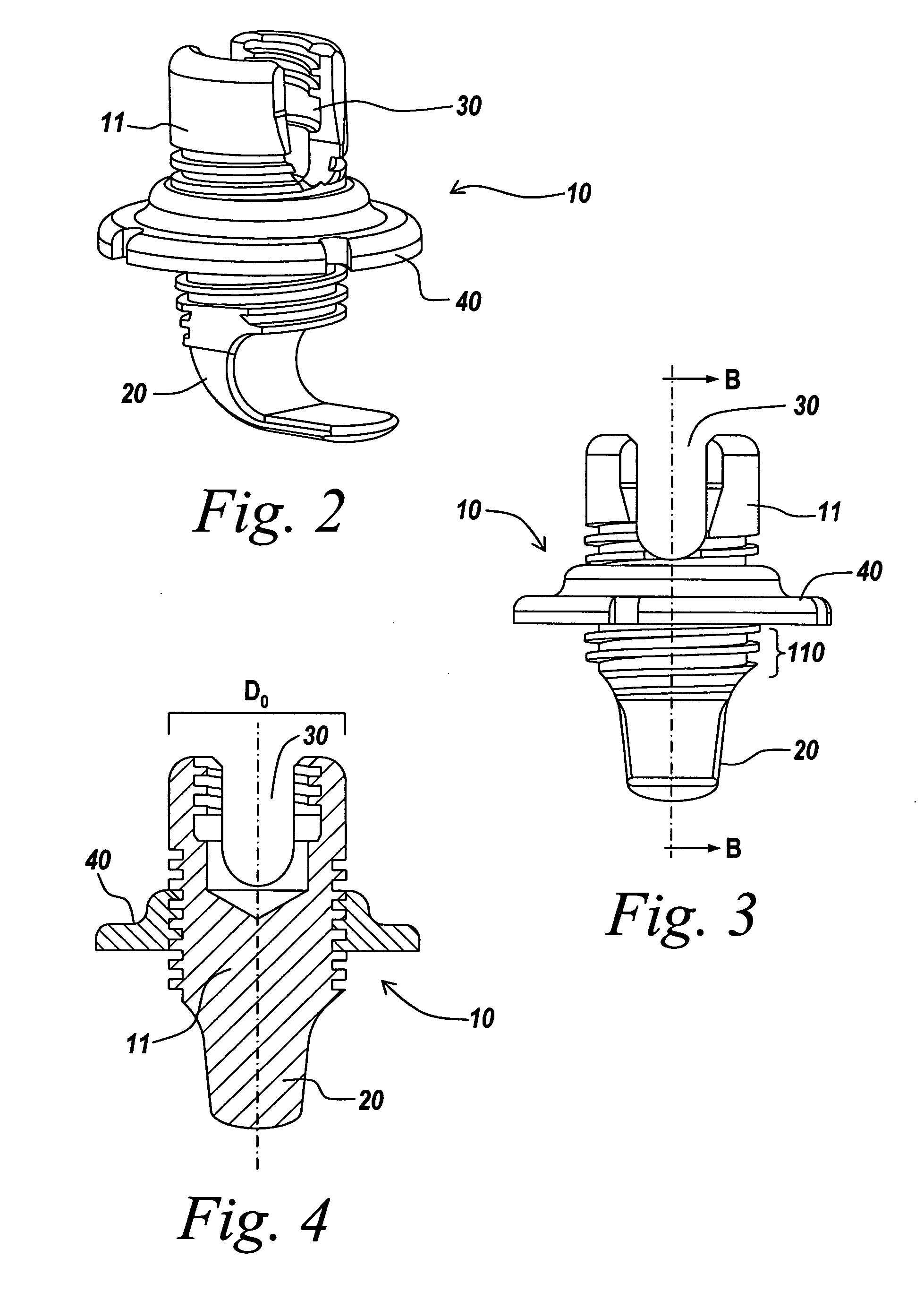
[0024] The present invention provides an improved orthopedic clamping hook assembly in a spinal fixation system. The invention will be described relative to use in the occipital region of a patient. One skilled in the art will recognize that the invention is not limited to use in the occipital bone, other bones, or in spinal surgery, and that the instrument and methods described herein can be adapted for use with any suitable surgical device to be moved into a selected position in a variety of medical procedures. The present invention will be described below relative to certain exemplary embodiments to provide an overall understanding of the principles of the structure, function, manufacture, and use of the instruments disclosed herein. Those skilled in the art will appreciate that the present invention may be implemented in a number of different applications and embodiments and is not specifically limited in its application to the particular embodiments depicted herein.

[0025]FIGS....


PUM


Abstract

An occipital clamping hook assembly includes a hook for engaging a first side of an occipital bone and a compressor movable relative to the hook for applying a compressive force to the occipital bone from a second side of the occipital bone. The occipital clamping assembly further includes a rod-receiving portion coupled to the hook for coupling a rod to the occipital bone engaged by the hook.

Description

FIELD OF THE INVENTION [0001] The present invention relates to spinal fixation devices used in orthopedic surgery. More particularly, the present invention relates to an orthopedic hook assembly for coupling a spinal rod to a bone, such as the occipital bone. BACKGROUND OF THE INVENTION [0002] Spinal fixation systems may be used in orthopedic surgery to align, stabilize and / or fix a desired relationship between adjacent vertebral bodies and / or the occipital bone in the skull. Such systems typically include a spinal fixation element, such as a relatively rigid fixation rod or plate, that is coupled to a bone by attaching the element to various anchoring devices, such as hooks, bolts, wires or screws. The fixation element can extend between two bone regions to effect stabilization, positioning, reduction or fixation of the bones. The spinal fixation element can have a predetermined contour that has been designed according to the properties of the target implantation site and, once ins...

Claims


Application Information

Patent Timeline
Patent Type & Authority Applications(United States)
IPC IPC(8): A61F2/30
CPCA61B17/7032A61B17/7035A61B17/7037A61B17/7056A61B17/7047A61B17/7055A61B17/7044
Inventor LAKE, MATTHEWHALL, MARKKONIECZYNSKI, DAVID
Owner DEPUY SPINE SARL
Why Eureka
Try Eureka