Illuminating ball

Inactive Publication Date: 2007-01-25
KO LI LIN
View PDF7 Cites 78 Cited by
  • Summary
  • Abstract
  • Description
  • Claims
  • Application Information

AI Technical Summary

Benefits of technology

[0006] An objective of the present invention is to increase the enjoyment of the ball game by providing an illuminating ball with multiple light em

Problems solved by technology

Since current designs for these types of balls follow specific and standardized guidelines, the only room left for change seems limited to th

Method used


Image

  • Illuminating ball
  • Illuminating ball
  • Illuminating ball

Examples


Embodiment Construction

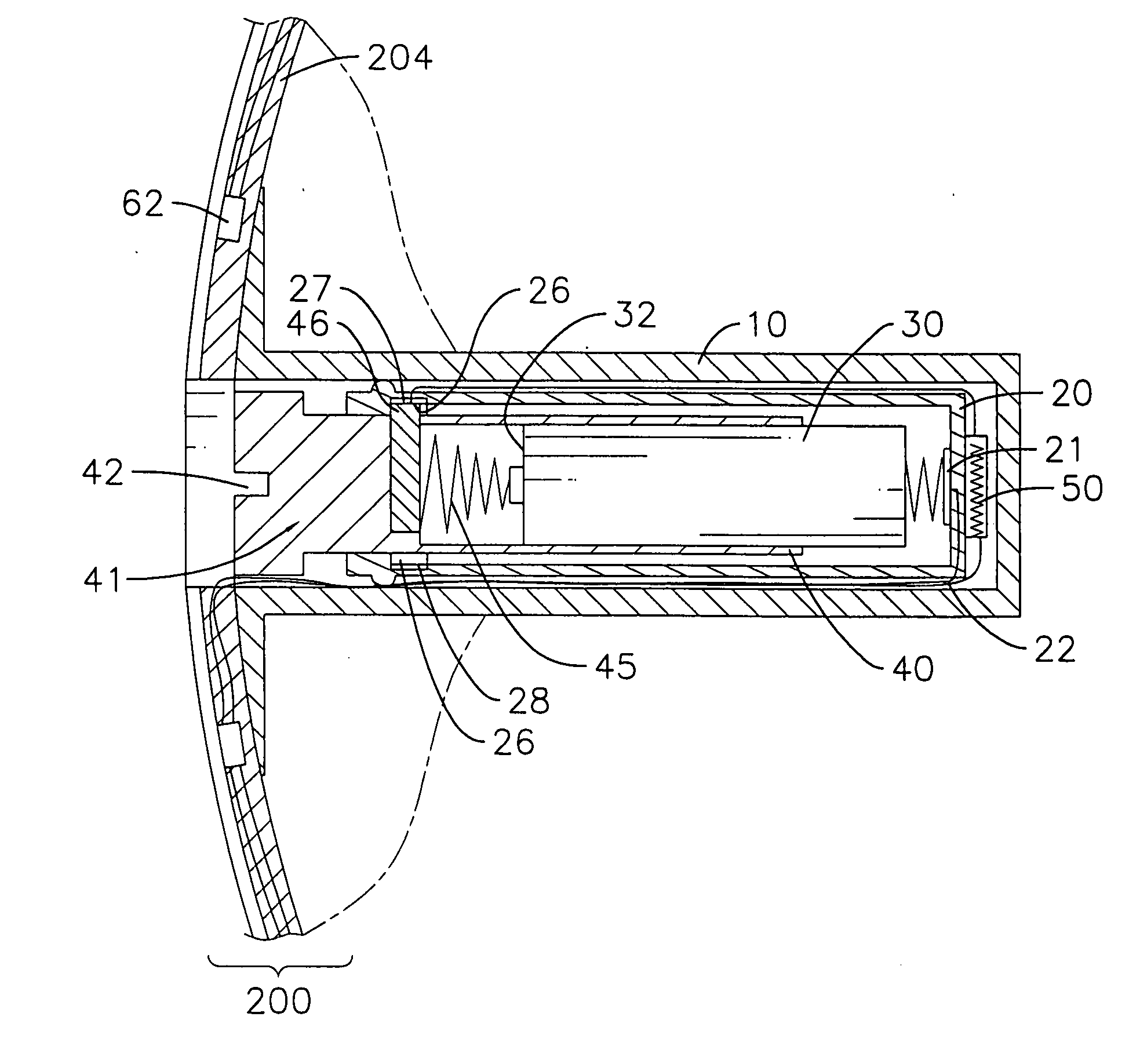
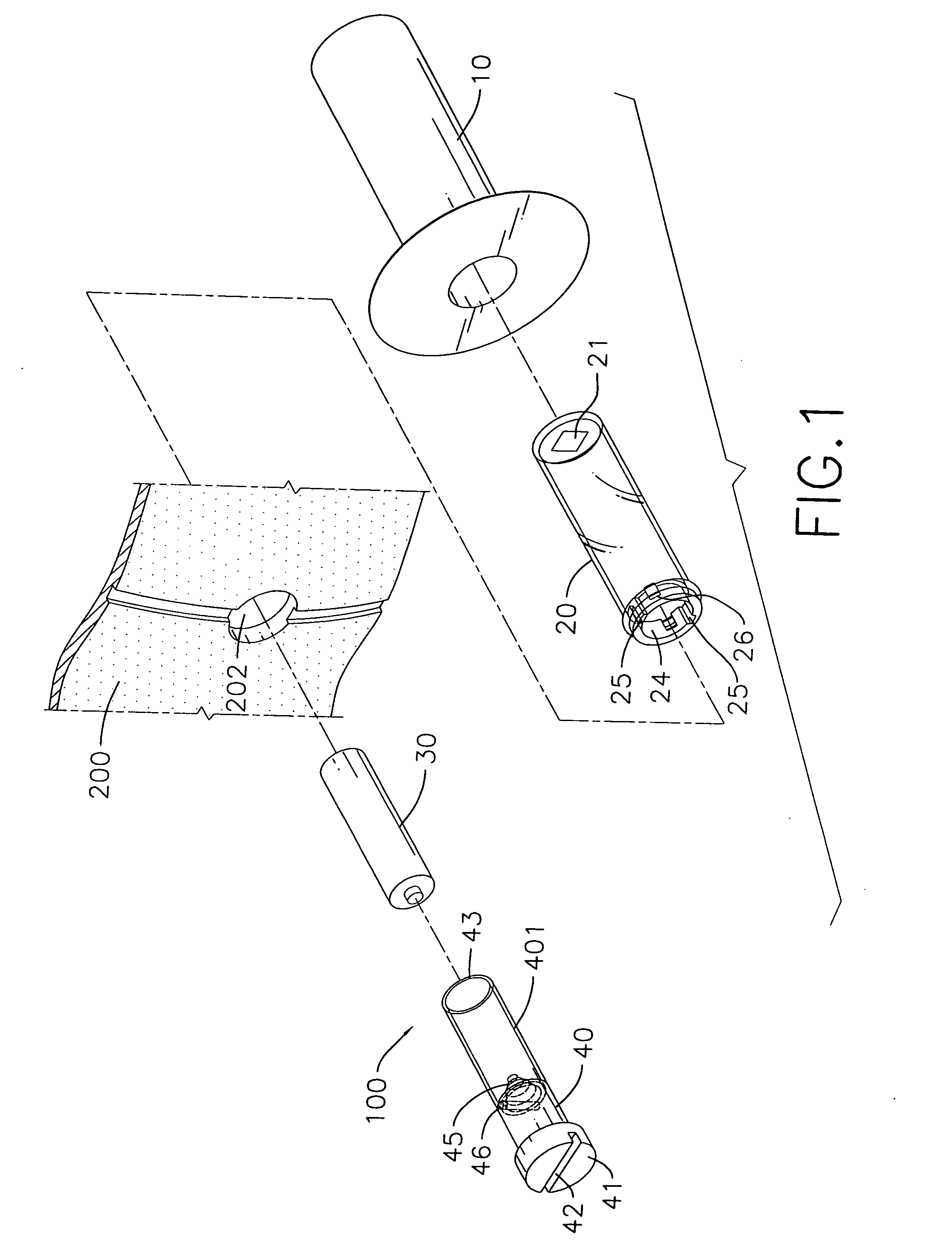
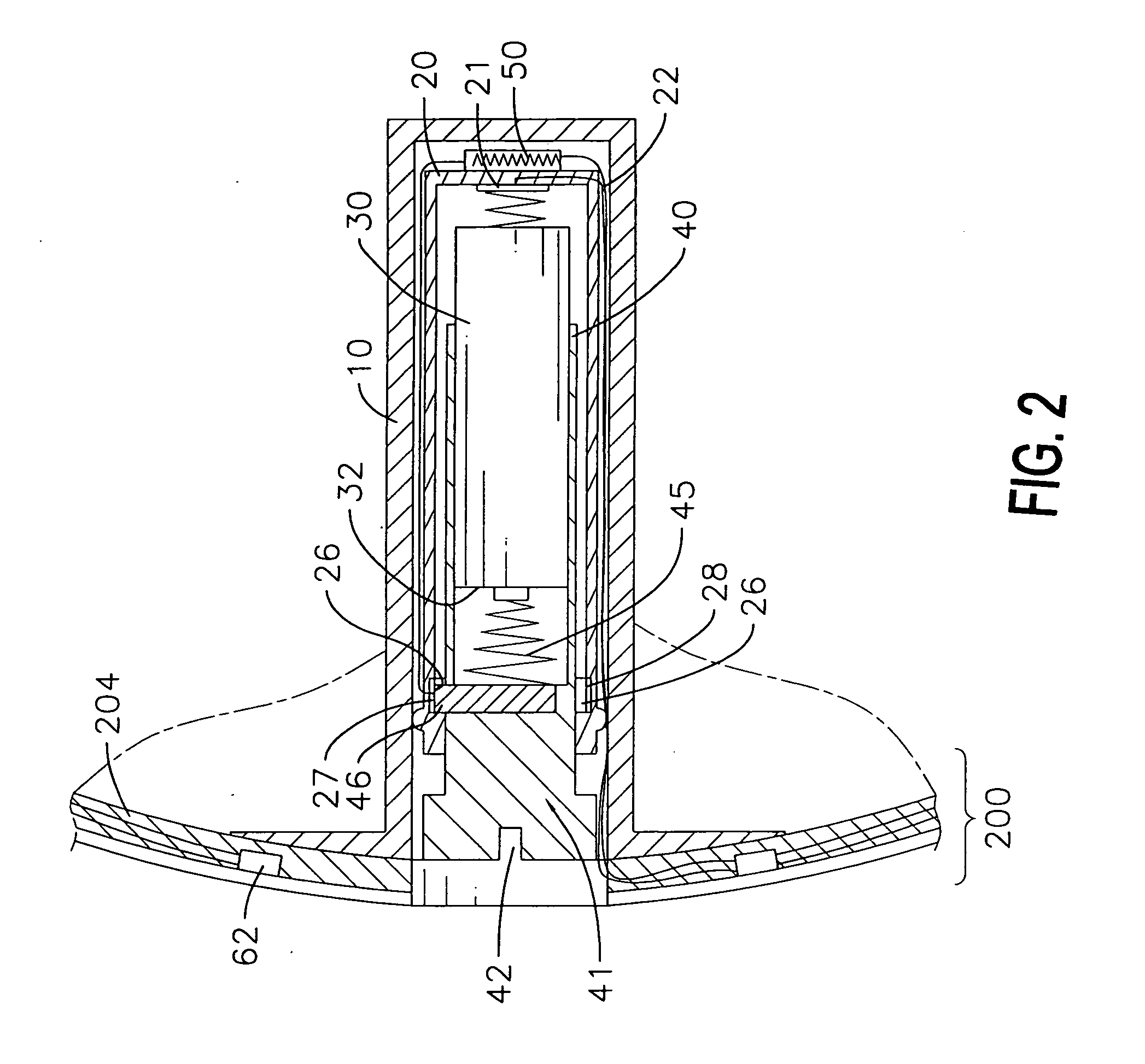
[0021] The present invention provides an illuminating ball (200) in which a power supply device (100) is embedded. The power supply device (100) connects to multiple light emitting elements (62) via wires, where the light emitting elements (62) are distributed in an exposed manner on an exterior periphery of the ball (200). In one aspect, when the ball (200) experiences vibration such as when bouncing, a vibration-triggered switch (50) connecting to the power supply device (100) can be automatically conducted, whereby these light emitting elements (62) are activated. The vibration-triggered switch can be automatically turned off if the ball (200) is in the static status. In another aspect, these light emitting elements (62) also can be manually activated regardless of the status of the ball (200).

[0022] An inflatable ball such as a basketball is basically composed of an inner bladder, a winding string layer forming around the bladder, an intermediate layer formed around the winding...


PUM


Abstract

An illuminating ball has embedded with a power supply device. Multiple output wires extending from the power supply device are electrically connected to multiple light emitting elements mounted over the ball. When the ball experiences vibration, a vibration-triggered switch in the power supply device can be automatically conducted to actuate the light emitting elements. On the contrary, the vibrating-triggered switch is automatically turned off if the ball is in the static status. Further, these light emitting elements also can be manually activated by controlling a switch.

Description

BACKGROUND OF THE INVENTION [0001] 1. Field of the invention [0002] The invention relates to an illuminating ball, and more particularly to a ball embedded with multiple light emitting components that can be manually activated or automatically activated when the ball experiences vibration. [0003] 2. Related Art [0004] Of all sports, ball games have long been the most popular, and include familiar forms for example, basketball, soccer, football and volleyball. Since current designs for these types of balls follow specific and standardized guidelines, the only room left for change seems limited to the material used and the surface patterns. [0005] In addition to the formal sport competitions in which people enjoy these ball games, it is far more common for them to invite a few good friends to play a game or two together for recreation. However, their enjoyment is often limited by the dull and unexciting design of the conventional ball. To overcome this shortcoming, the present inventi...

Claims


Application Information

Patent Timeline
IPC IPC(8): A63B43/06
CPCA63B43/06A63B41/00
Inventor KO, LI-LIN
Owner KO LI LIN
Why Eureka
Try Eureka