Compression Hose Clamp

a compression hose and clamping technology, applied in the direction of hose connection, clothing, sanitary products, etc., can solve the problems of clamp sticking and being difficult to loosen, thermal changes, and problems such as the clamping to stick and be difficult to loosen

Inactive Publication Date: 2007-02-01
EPICOR IND
View PDF18 Cites 36 Cited by
  • Summary
  • Abstract
  • Description
  • Claims
  • Application Information

AI Technical Summary

Problems solved by technology

Several major problems may arise with this type of clamp.
Such extrusions not only damage the hose but also tend to cause the clamp to stick and be difficult to loosen again when necessary.
Another problem is associated with thermal changes.
A further problem is to maintain a fluid-tight seal throughout the intended life of the assembly, without requiring the clamp to be re-tightened.

Method used


Image

  • Compression Hose Clamp
  • Compression Hose Clamp
  • Compression Hose Clamp

Examples


Embodiment Construction

[0017] The present invention relates to the field of hose clamps, and provides a means for increasing the hose clamp unit loading. In addition, this invention provides spring compensation to help overcome hose shrinkage and expansion during thermal cycling. The following description is presented to enable one of ordinary skill in the art to make and use the invention and to incorporate it in the context of particular applications. Various modifications, as well as a variety of uses in different applications will be readily apparent to those skilled in the art, and the general principles defined herein may be applied to a wide range of embodiments. Thus, the present invention is not intended to be limited to the embodiments presented, but is to be accorded the widest scope consistent with the principles and novel features disclosed herein.

[0018] Overview of the Invention:

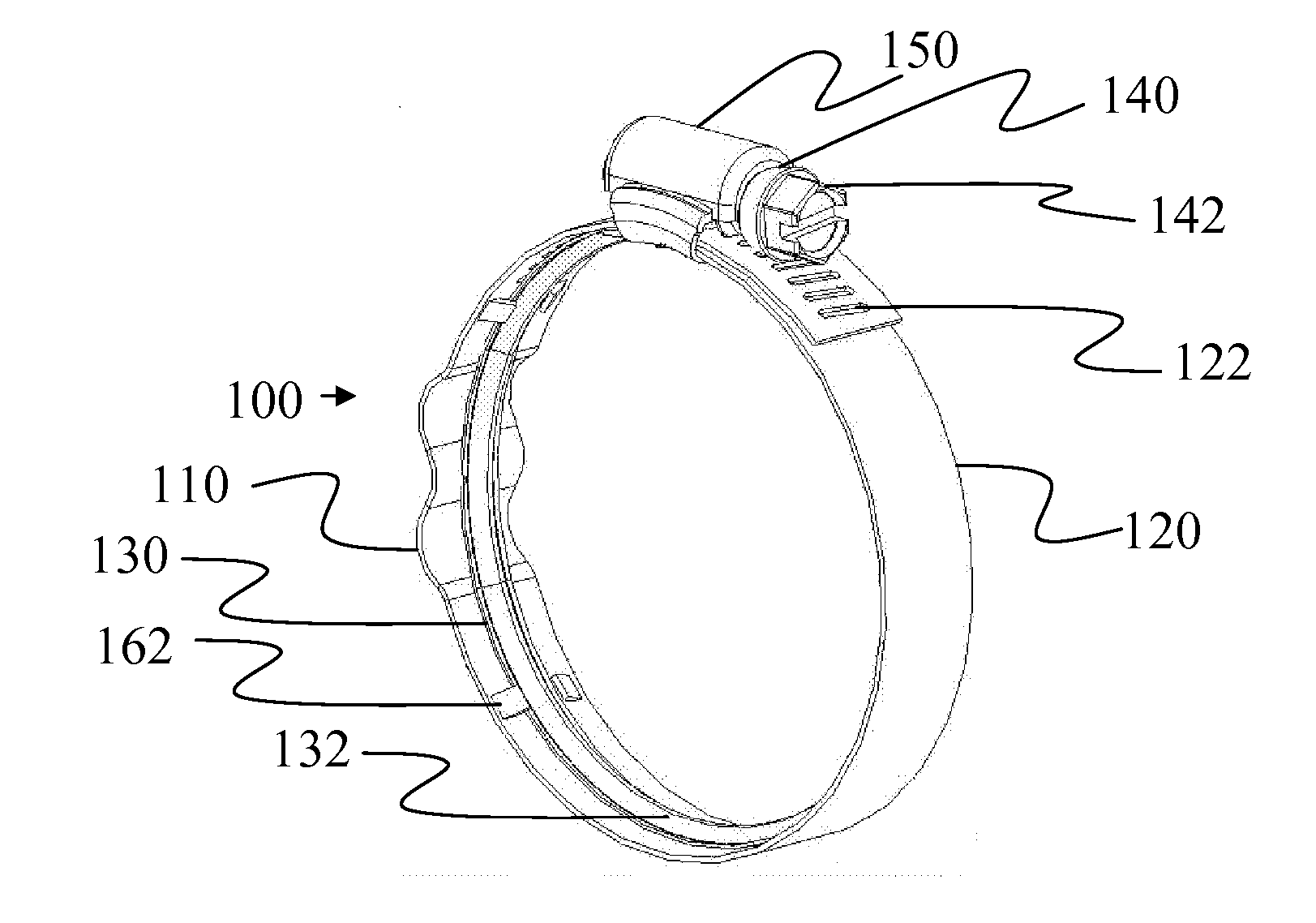
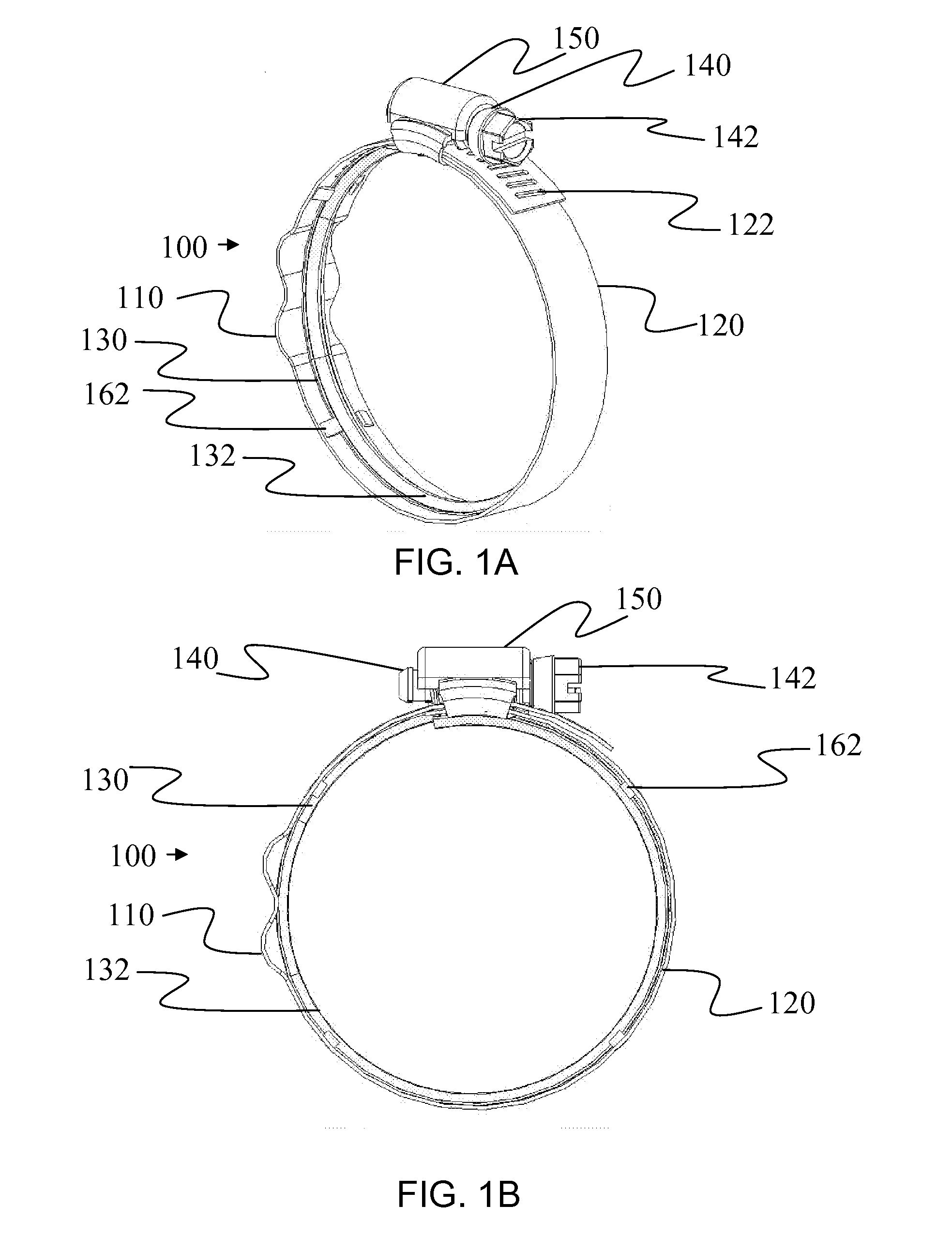
[0019] As depicted in FIGS. 1A and 1B, the present invention is a hose clamp 100 that uses a wave-form 110 integ...


PUM


Abstract

A hose clamp 100 including a band 120 with an integrated wave-form 110 formed in the band 120 for spring compensation during thermal cycling and material aging, and notches 122 formed in the band 120; a housing 150; a worm gear screw 140 for tensioning the hose clamp; a compression liner 130 inserted in the inside circumference of the band 120 to increase clamp unit loading by concentrating the load radially inward around and through the circumference of the band120; and an attachment means to secure the compression liner 130 in place with the band 120.

Description

CROSS-REFERENCE [0001] This application claims the benefit of U.S. Provisional Application Ser. No. 60 / 703,116, filed Jul. 27, 2005, titled Wave-form, Compression Hose Clamp. The present application is related by the same inventors for all applications; Watkins Crockett IV, Jonathan L. Chilson, Duane M. Farmer, Rex Fayter, David A. Ramsey, Gene C. Holz, Brian J. Adamo. The U.S. Provisional Application Ser. No. 60 / 703,116, filed Jul. 27, 2005, titled Wave-form, Compression Hose Clamp is hereby incorporated in its entirety by reference.FIELD OF THE INVENTION [0002] The present invention relates to a hose clamp, and provides a means for increasing the clamp unit loading. In addition, this invention provides spring compensation to help overcome hose shrinkage and expansion during thermal cycling. BACKGROUND OF THE INVENTION [0003] Worm gear screw hose clamps are very well known, the clamp being tightened or loosened by rotation of the worm gear screw in the respective direction, the rot...

Claims


Application Information

Patent Timeline
Patent Type & Authority Applications(United States)
IPC IPC(8): F16L33/00
CPCF16L33/08Y10T24/1457Y10T24/1427
Inventor CROCKETT, WATKINS IVCHILSON, JONATHAN L.FARMER, DUANE M.FAYTER, REXRAMSEY, DAVID A.HOLZ, GENE C.ADAMO, BRIAN J.
Owner EPICOR IND
Why Eureka
Try Eureka