Rolled stent with waveform perforation pattern

a waveform and stent technology, applied in the field of vascular disease treatment, can solve the problems of clots and coils falling out of the sac, stroke or the symptoms of stroke, and achieve the effect of immediate and complete sealing

Inactive Publication Date: 2002-10-17
TYCO HEALTHCARE GRP LP
View PDF12 Cites 54 Cited by
  • Summary
  • Abstract
  • Description
  • Claims
  • Application Information

AI Technical Summary

Problems solved by technology

Occlusion of the coronary arteries, for example, is a common cause of heart attack.
The mass and size of the tumor can cause a stroke or the symptoms of stroke, requiring surgery for removal of the tumor or other remedial intervention.
This technique has reportedly resulted in clots and coils falling out of the sac, and the technique is not used on wide-neck aneurysms.
However, these techniques do not always effect an immediate and complete seal of the aneurysm from the high pressure of the circulatory system, and rupture, leakage and deadly complications occur.
Aneurysm rupture and bleeding during surgical clipping and shortly after the clip placement is a significant problem and add difficulty to the procedure.
Thus the article illustrates that GDC's do not always work, and when they fail they may leave the patient in a critical condition.
As illustrated in the article, bleeding during surgical clipping and shortly after the clip placement is also a frequent problem.
The physical characteristics of prior art balloon expandable stents and self expanding stents make them clearly unsuitable for intra-cranial use, because of their delivery profile and tendency to temporarily occlude the vessel during deployment.
Palmaz stents, Palmaz-Schatz.TM. stents, Wallstents, Cragg stents, Strecker stents and Gianturco stents and other stents are too rigid to allow placement in the cerebral blood vessels, some require a balloon for deployment, and all are too open to immediately occlude an aneurysm.

Method used


Image

  • Rolled stent with waveform perforation pattern
  • Rolled stent with waveform perforation pattern
  • Rolled stent with waveform perforation pattern

Examples


Embodiment Construction

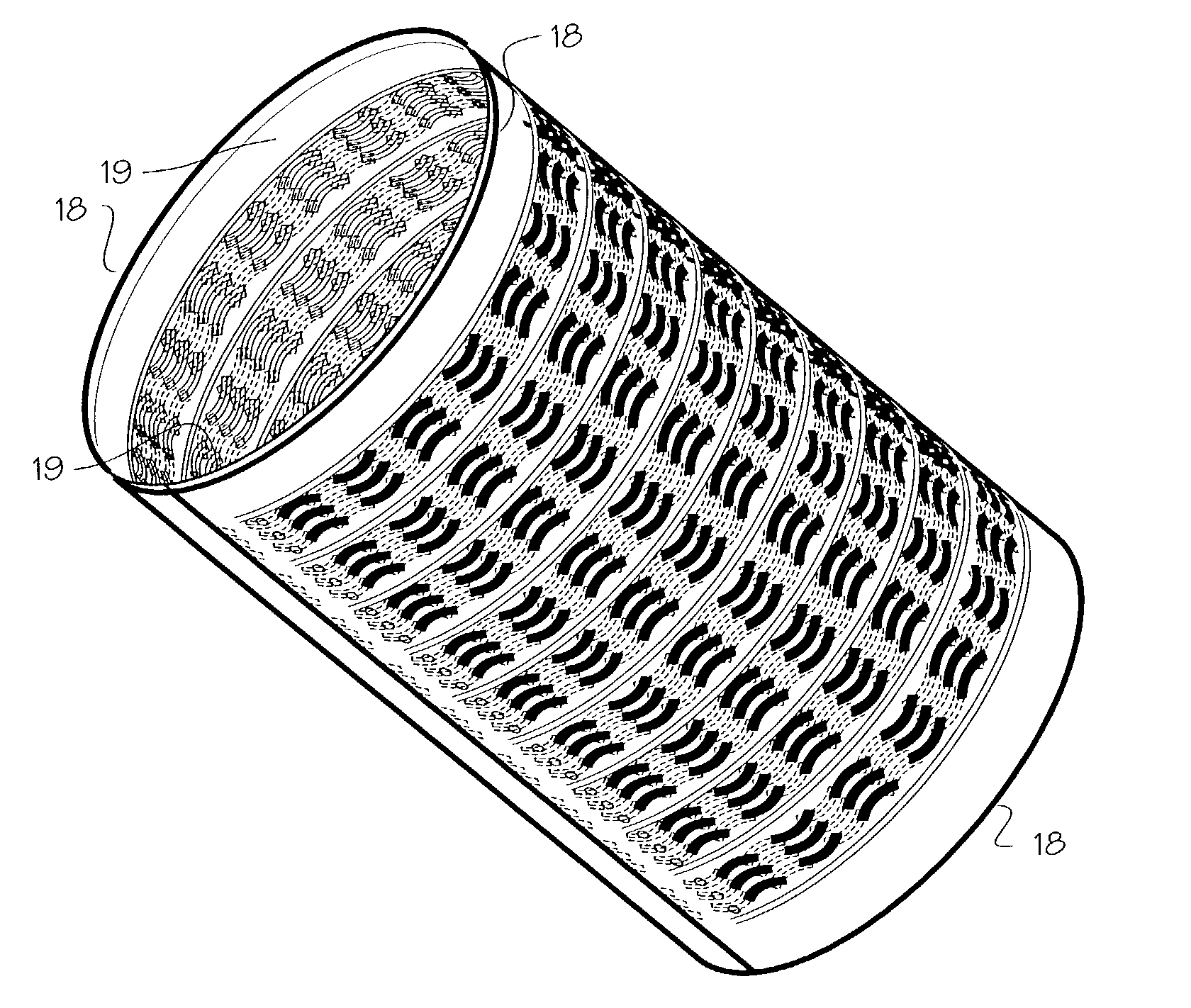
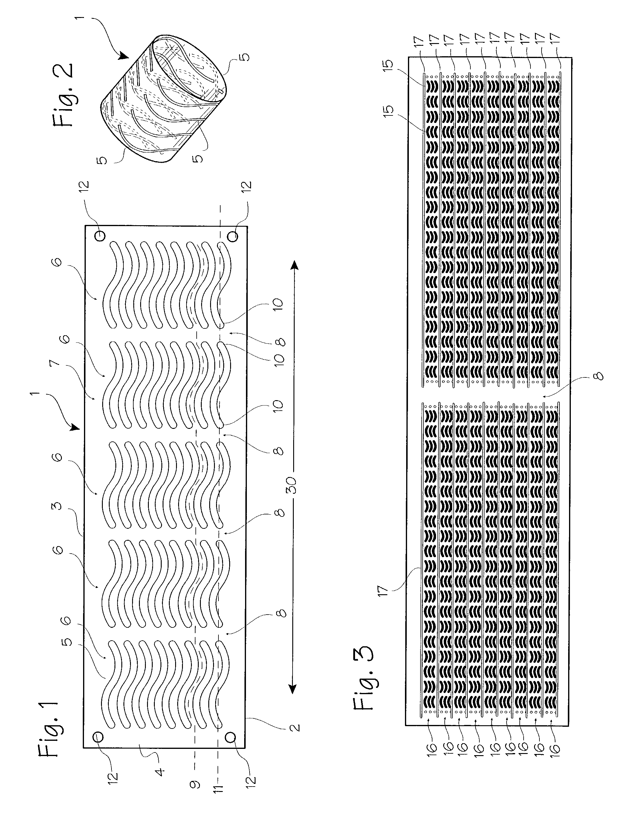
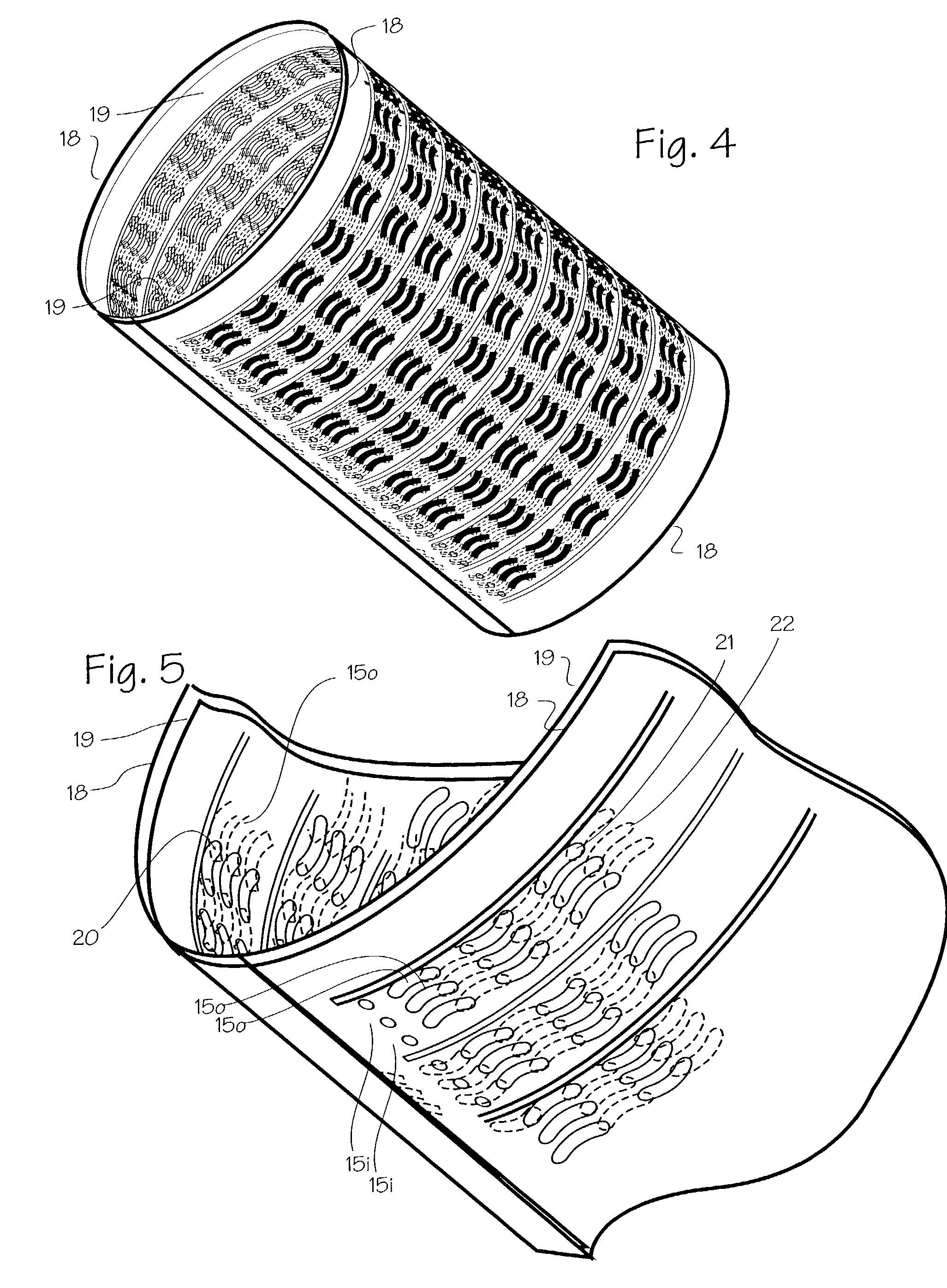
[0017] FIG. 1 shows a basic form of the stent 1. The basic embodiment comprises a sheet 2 of Elgiloy.TM. about 0.0025 to 0.025 mm thick (0.1 mils to 1 mil, or 0.0001 to 0.0010 inches). Referring to FIG. 1, the wrap length represented by transverse edge 3 will be about 6-75 mm, allowing the stent to expand to diameters from about 1 mm to about 6 mm with approximately two to three layers after expansion. The bridge length represented by axial edge 4 (or the longitudinal edge) will vary according to the width of the aneurysm, occlusion or other defect which must be bridged by the stent, and may vary from 2 to 20 mm, for example. The stent is tempered or formed so that it resiliently unrolls and expands to a diameter of approximately 1 mm to 6 mm, and provides a slight compliance mismatch with the intra-cranial arteries which have internal diameters of about 1 mm to 6 mm.

[0018] The stent may be formed of Elgiloy.TM., nitinol, stainless steel, plastic or other suitable material. The sten...


PUM


Abstract

A stent fabricated from a rolled sheet. The sheet is perforated with wave form perforations to provide flexibility during insertion and in the body.

Description

[0001] This application is a continuation of U.S. application Ser. No. 09 / 487,412 filed Jan. 18, 2000, now U.S. Pat. No. 6,406,490, which is a continuation of U.S. application Ser. No. 09 / 087,600 filed May 29, 1998, now U.S. Pat. No. 6,015,433.FIELD OF THE INVENTIONS[0002] This invention relates to treatments for vascular disease.BACKGROUND OF THE INVENTIONS[0003] In our prior patent applications, Intracranial Stent and Method of Use, U.S. patent application Ser. No. 08 / 707,996 (Sep. 18, 1996) and Ser. No. 08 / 761,110 (Dec. 9, 1996), we disclosed numerous embodiments of stents and stent delivery systems which enable surgeons to place stents deep within the brain. The inventions described in our prior applications were developed with the goal of providing new and better therapies for certain types of vascular disease for which the present day therapies are widely regarded as inadequate. Vascular disease includes aneurysms which can rupture and cause hemorrhage, atherosclerosis which c...

Claims


Application Information

Patent Timeline
Patent Type & Authority Applications(United States)
IPC IPC(8): A61F2/92
CPCA61F2/91A61F2/915A61F2002/9155A61F2002/91533A61F2/92
Inventor ROTH, NOAH M.
Owner TYCO HEALTHCARE GRP LP
Why Eureka
Try Eureka