Low torque hydrodynamic lip geometry for bi-directional rotation seals

a hydrodynamic lip geometry and bi-directional rotation technology, applied in the direction of engine seals, mechanical equipment, engine components, etc., to achieve the effect of prolonging the life of the seal

Active Publication Date: 2006-09-28
KALSI ENG
View PDF86 Cites 54 Cited by
  • Summary
  • Abstract
  • Description
  • Claims
  • Application Information

AI Technical Summary

Benefits of technology

[0029] Briefly, the invention is preferably a generally circular, hydrodynamically lubricating, dynamic sealing lip geometry that is directed at prolonging seal life in

Problems solved by technology

Although such seals perform well under certain conditions, there are other conditions in which their performance is deficient.
One such set of difficult conditions is where the seal is subject to both clockwise and counter-clockwise rotation and where increased lubricant film thickness is desirable.
As a result, the dynamic sealing interface is less well lubricated toward the environment-side which causes undesirable wear, torque and seal-generated heat—particularly when one or more of the following conditions are encountered: Thin viscosity lubricants, which are less than optimum for lubrication; High differential pressure across the seal; High ambient geothermal temperature; Shaft materials and configurations that interfere with heat transfer; High initial seal compression; High rotary speeds; and Closely spaced redundant seals that concentrate seal-generated heat.
For example, media resistance problems, gas permeation problems, swelling, compression set and pressure-related extrusion damage all become worse at higher temperatures.
The prior art seals cannot be used in some high speed or high-pressure applications simply because the useful temperature range of the seal material is exceeded due to seal-generated heat.
Additionally, the bi-directional rotation prior art seals do not provide sufficient lubrication if the sealing lip incorporates harder materials—such as reinforced polytetrafluoroethylene (“PTFE”) based plastic.
Typically, seal lif

Method used


Image

  • Low torque hydrodynamic lip geometry for bi-directional rotation seals
  • Low torque hydrodynamic lip geometry for bi-directional rotation seals
  • Low torque hydrodynamic lip geometry for bi-directional rotation seals

Examples


Embodiment Construction

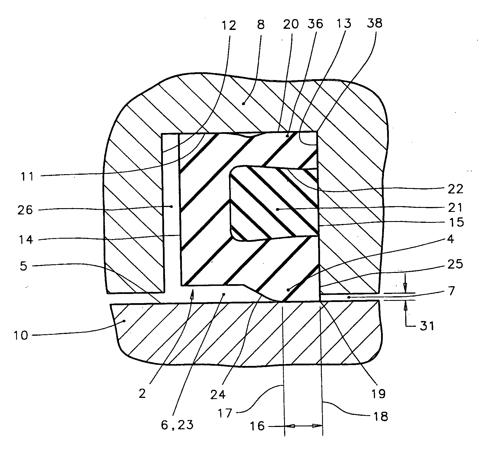
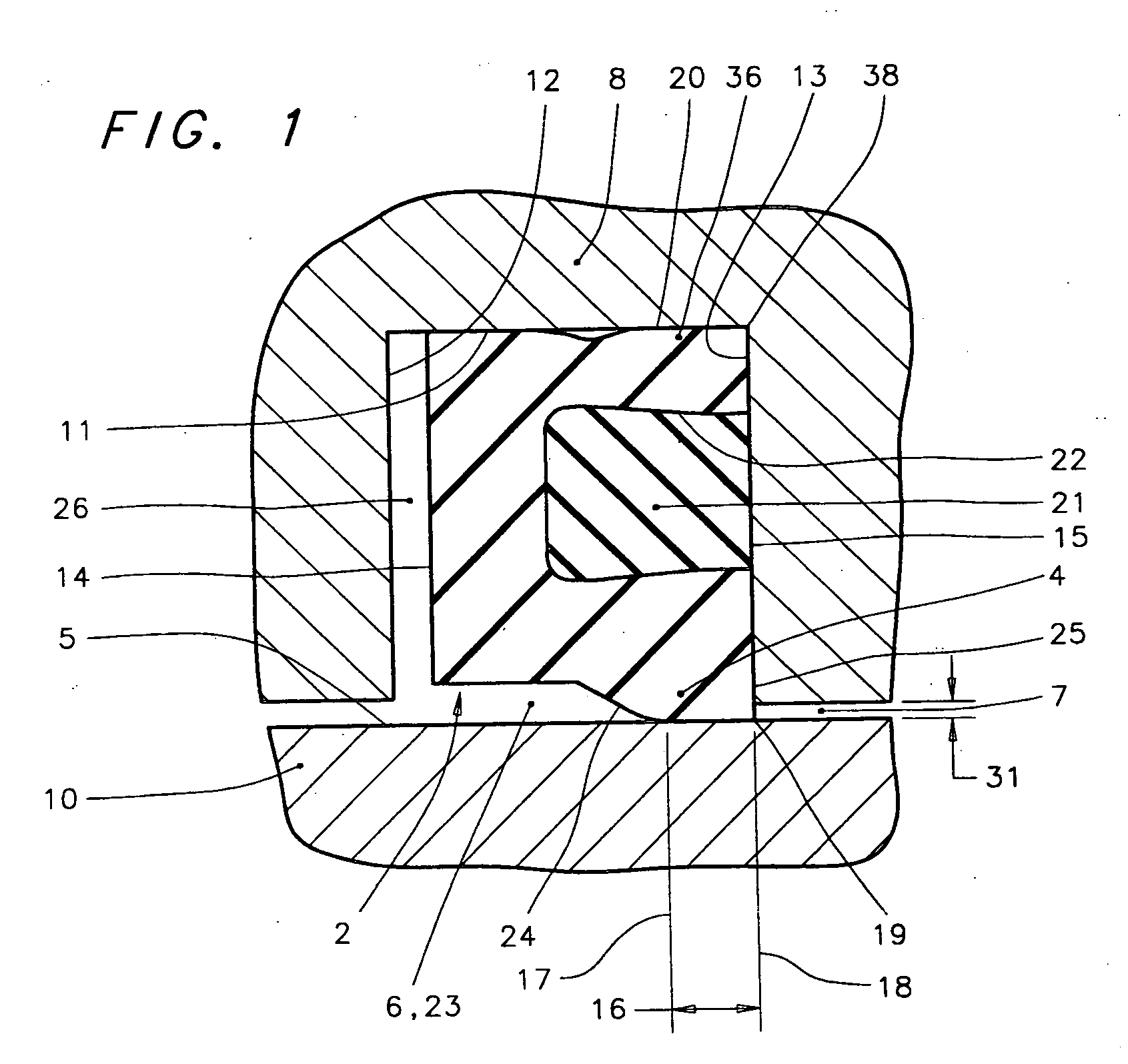
[0056]FIGS. 1-2B should be studied together, in order to attain a more complete understanding of the invention, because the total concept cannot be perfectly conveyed by any single figure. Features throughout this specification that are represented by like numbers have the same function. For orientation purposes, it should be understood that in the cross-sectional views of FIGS. 1, 1D-1F and 4-13, the cutting plane of the cross-section is aligned with and passes through the theoretical axis of the seal; and the sketching plane of the schematic views of FIGS. 16-17 is at right angles to the theoretical axis of a seal that is configured for sealing against a relatively rotatable shaft.

Description of FIG. 1

[0057]FIG. 1 is a fragmentary cross-sectional view that provides a general overview of how the preferred embodiment of the present invention is employed when assembled into a machine. A rotary seal 2 of generally circular, ring-like configuration includes at least one dynamic lip 4...


PUM


Abstract

A hydrodynamically lubricating geometry for the generally circular dynamic sealing lip of rotary seals that are employed to partition a lubricant from an environment. The dynamic sealing lip is provided for establishing compressed sealing engagement with a relatively rotatable surface, and for wedging a film of lubricating fluid into the interface between the dynamic sealing lip and the relatively rotatable surface in response to relative rotation that may occur in the clockwise or the counter-clockwise direction. A wave form incorporating an elongated dimple provides the gradual convergence, efficient impingement angle, and gradual interfacial contact pressure rise that are conducive to efficient hydrodynamic wedging. Skewed elevated contact pressure zones produced by compression edge effects provide for controlled lubricant movement within the dynamic sealing interface between the seal and the relatively rotatable surface, producing enhanced lubrication and low running torque.

Description

CROSS-REFERENCE TO RELATED APPLICATIONS [0001] This application claims the benefit of U.S. Provisional Application Ser. No. 60 / 664,662 filed on Mar. 22, 2005, entitled “Rotary Shaft Seal,” and claims the benefit of U.S. Provisional Application Ser. No. 60 / 755,975 filed Jan. 4, 2006, entitled “Hydrodynamic Rotary Seal.”STATEMENT REGARDING FEDERALLY SPONSORED RESEARCH OR DEVELOPMENT [0002] This invention was made with United States government support under Contract No. DE-FG02-05ER84206 awarded by the Department of Energy. The United States government therefore has certain rights in this invention.BACKGROUND OF THE INVENTION [0003] 1. Field of the Invention [0004] The present invention relates generally to lubrication of rotary seals in order to prolong seal life and reduce running torque, wear and self-generated heat. The rotary seals are suitable for environmental exclusion and lubricant retention, and more particularly relate to lubrication of seals that may be exposed to high diff...

Claims


Application Information

Patent Timeline
IPC IPC(8): F16J15/32
CPCF16J15/3208F16J15/3236F16J15/324F16J15/3244
Inventor DIETLE, LANNIE L.SCHROEDER, JOHN E.
Owner KALSI ENG
Why Eureka
Try Eureka