Valve for the substantially gas-tight interruption of a flow path

a flow path and substantially gastight technology, which is applied in the direction of valve member-seat contacts, mechanical equipment, transportation and packaging, etc., can solve the problems that neither the drive nor the connection between the drive and the outer disk portion is exposed to high forces, and achieves low sealing wear and high pressure loads.

Active Publication Date: 2013-10-08
VAT HLDG AG
View PDF22 Cites 11 Cited by
  • Summary
  • Abstract
  • Description
  • Claims
  • Application Information

AI Technical Summary

Benefits of technology

[0018]The object of the invention is therefore to solve the above-described problems and to provide a valve of the type stated in the introduction which is built as simply and compactly as possi...

Problems solved by technology

Moreover, neither the prevailing differential pressure, nor a contact pressing force, acts upon the drive of the valve...

Method used


Image

  • Valve for the substantially gas-tight interruption of a flow path
  • Valve for the substantially gas-tight interruption of a flow path
  • Valve for the substantially gas-tight interruption of a flow path

Examples


Embodiment Construction

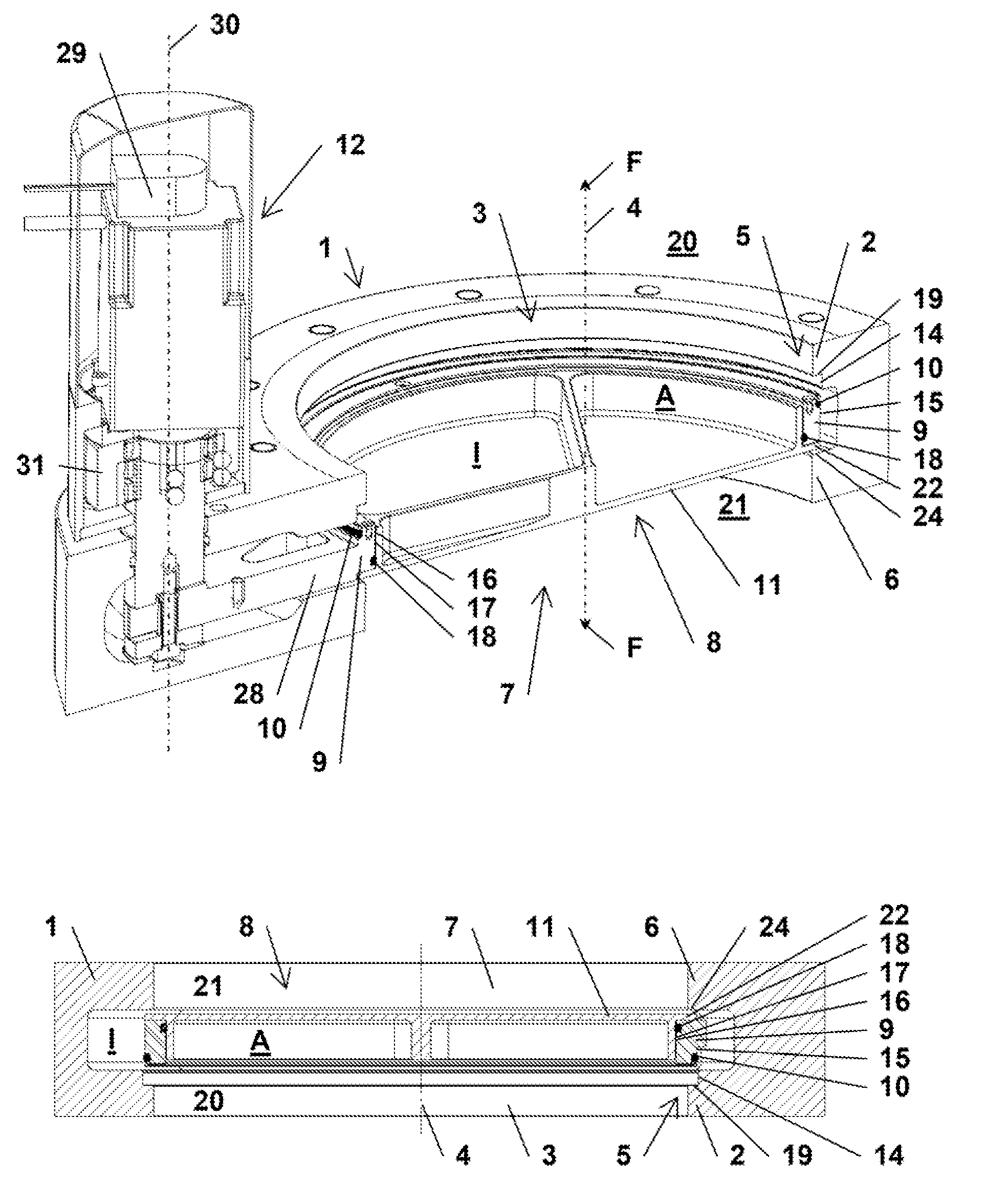
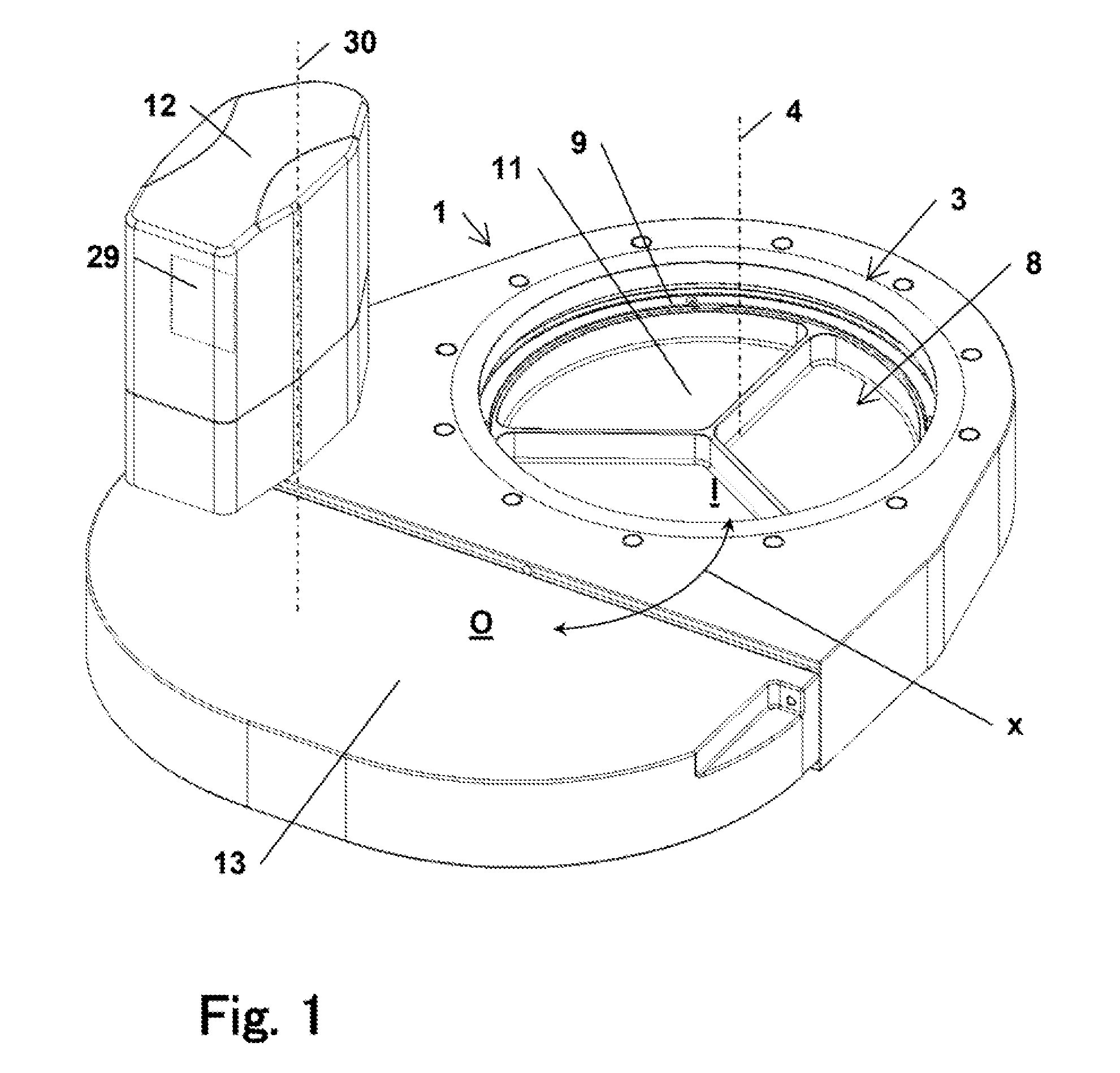
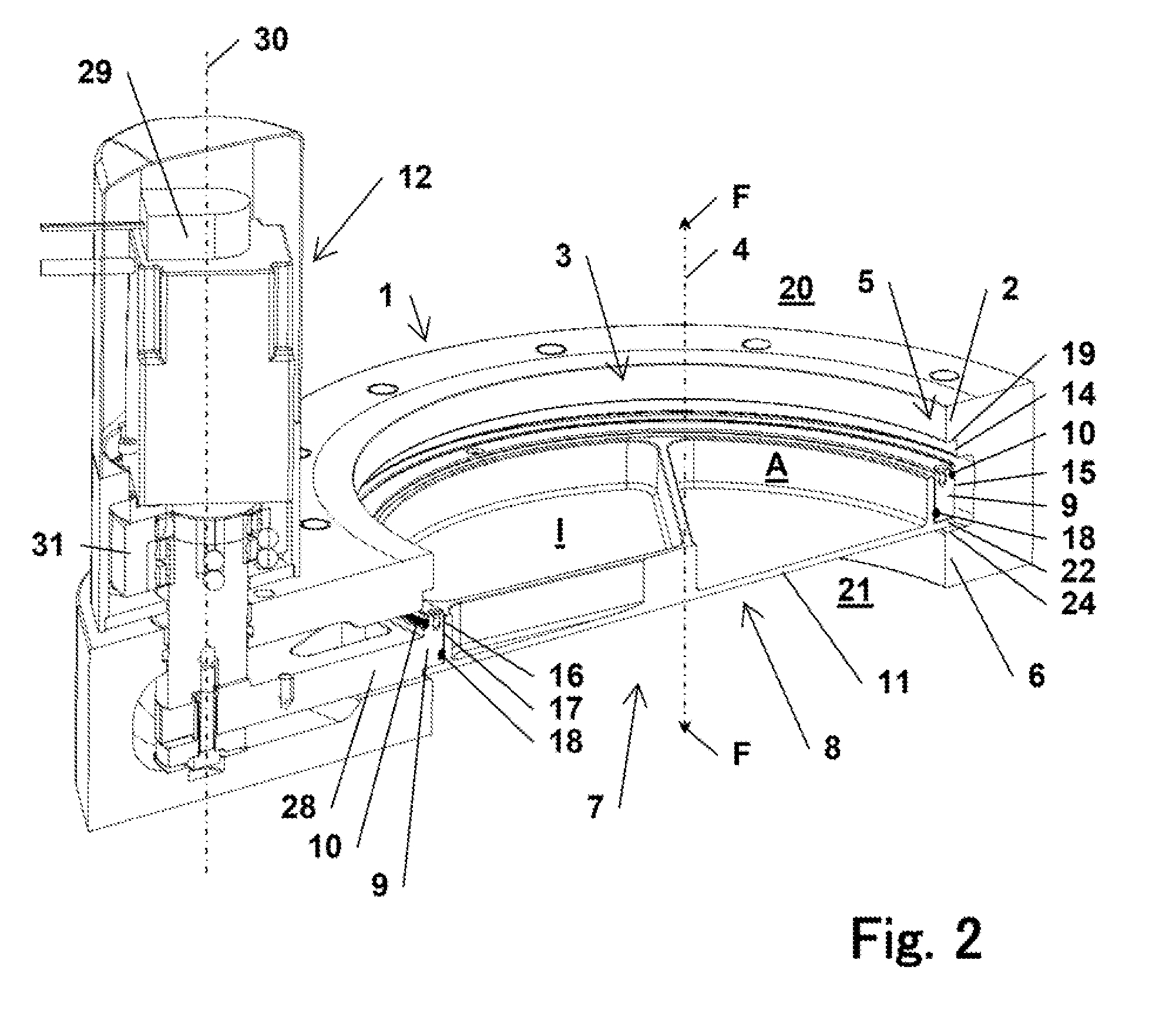
[0056]FIGS. 1 to 4d show a joint, exemplary embodiment of a valve according to the invention in different states, from different views and in different degrees of detailing. These figures are therefore described jointly, wherein reference symbols and features which have already been explained in preceding figures are, in part, not discussed anew.

[0057]In FIGS. 1 to 4d, one possible embodiment of the valve according to the invention, in the form of a shuttle valve, is represented. The valve for the substantially gastight interruption of a flow path F, which in FIG. 2 is symbolized by the use of arrows, possesses a valve housing 1, which has a first opening 3 and an opposite second opening 7. Both openings 3 and 7 have a circular cross section. In the closed setting C of a valve disk 8, FIGS. 3b, 3c, 4b and 4c, the two openings 3 and 7 are mutually separated in a gastight manner by means of the valve disk 8, while in the open setting O of the valve disk 8 the two openings 3 and 7 are ...


PUM


Abstract

A valve for the gastight interruption of a flow path is disclosed. A valve housing includes a first opening and a valve seat. A valve disk includes an inner disk portion, which is linearly movable relative to an outer disk portion so that, in a closed setting, a pressure differential acts substantially upon the movable inner disk portion, which is supported on the valve housing. The valve seat has a radially inward pointing first inner face and the outer disk portion has a radially outward pointing first outer face, wherein in the closed setting there exists a radial sealing contact with the first inner face. The outer disk portion has a radially inward pointing second inner face and the inner disk portion has a radially outward pointing second outer face, having a radially sealing contact with the second inner face.

Description

[0001]The present application claims priority to European Patent Application No.: 11175689.7, which was filed in the EPO on Jul. 28, 2011, and which is herein incorporated by reference in its entirety.BACKGROUND OF THE INVENTION[0002]1. Field of the Invention[0003]The invention relates to a valve for the substantially gastight interruption of a flow path, according to the preamble to claim 1. Such valves, particularly in the form of shuttle valves or slide valves, are used, above all, in vacuum technology.[0004]2. Description of the Background Art[0005]A valve according to the preamble to claim 1 is known from US 2007 / 0138424 (Geiser), which is regarded as the closest prior art.[0006]Valves of the type stated in the introduction are known in different embodiments from the prior art and are used, in particular, in vacuum chamber systems in the field of IC, semiconductor or substrate production, which must take place in a protected atmosphere as far as possible without the presence of...

Claims


Application Information

Patent Timeline
IPC IPC(8): F16K25/00
CPCF16K51/02F16K3/10Y10T137/598F16K1/16F16K25/00
Inventor LAMPRECHT, MICHAELWEISS, WOLFGANG
Owner VAT HLDG AG
Why Eureka
Try Eureka